

HDLbits day1
一、Getting Started
1、Getting Started
Build a circuit with no inputs and one output. That output should always drive 1 (or logic high).
建立一个没有输入和一个输出的电路。该输出应始终驱动 1(或逻辑高电平)
1 module top_module( output one );
2
3 // Insert your code here
4     assign one = 1'b1;
5
6 endmodule
2、Output Zero
Build a circuit with no inputs and one output that outputs a constant 0
构建一个没有输入和一个输出的电路,输出一个常数0
1 module top_module(
2     output zero
3 );// Module body starts after semicolon
4
5 endmodule
二、Verilog Language
1、Basics
1.1、simple wire
创建一个具有一个输入和一个输出的模块,其行为类似于电线。
1)与物理线不同,Verilog 中的线(和其他信号)是有方向的。这意味着信息仅在一个方向上流动,从(通常是一个)源到接收器(源通常也称为驱动器,将值驱动到线路上)。在 Verilog “连续赋值” (
assign left_side = right_side;) 中,右侧的信号值被驱动到左侧的导线上。赋值是“连续的”,右边的值发生变化,左边的值立刻发生变化2)模块上的端口也有方向(通常是输入或输出)。输入端口由模块外部的某些东西驱动,而输出端口由外部的某些东西驱动。从模块内部看,输入端口是驱动器或源,而输出端口是接收器。
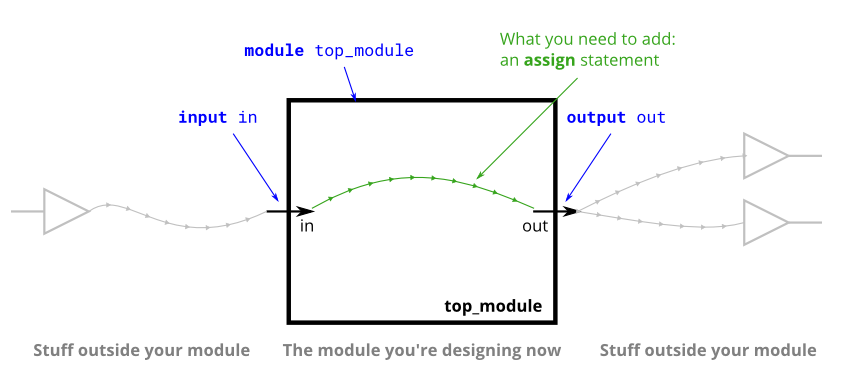
module top_module( input in, output out );
assign out=in;
endmodule
1.2、Four wires
创建一个具有 3 个输入和 4 个输出的模块,其行为类似于进行这些连接的电线:
a -> w
b -> x
b -> y
c -> z
1)下图说明了电路的每个部分如何对应 Verilog 代码的每一位。从模块外部看,有三个输入端口和四个输出端口。
2)当您有多个分配语句时,它们在代码中出现的顺序无关紧要。与编程语言不同,赋值语句(“连续赋值”)描述事物之间的联系,而不是将值从一个事物复制到另一个 事物的动作。
3)现在也许应该澄清一个潜在的混淆来源:这里的绿色箭头代表电线之间的连接,但它们本身并不是电线。模块本身已经声明了 7 根线(命名为 a、b、c、w、x、y 和 z)。这是因为除非
input另有output说明,否则声明实际上声明了一条线。写法input wire a同理input a。因此,这些assign语句不是在创建连线,而是在创建已经存在的 7 条连线之间的连接。

module top_module(
     input a,b,c,
     output w,x,y,z );
     assign w=a,x=b, y=b,z=c;

endmodule
1.3、inverter
创建一个实现非门的模块。
1)这个电路类似于电线,但略有不同。当从电线连接到电线
in时,out我们将使用“非门”而不是普通电线。2)使用分配语句。该
assign语句将连续驱动inon的逆out。
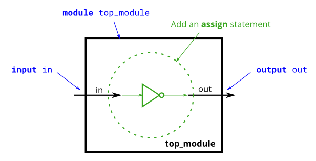
module top_module( input in, output out );
 assign out=!in;
endmodule
1.4、AND gate
创建一个实现与门的模块。
1)该电路现在有三根导线(
a、b和out)。电线a和b已经有输入端口驱动到它们的值。但是电线out目前不是由任何东西驱动的。编写一个用信号和的 ANDassign驱动的语句。2)将信号描述为被驱动(具有由附加的东西决定的已知值)或不被某物驱动。
Input wires由模块外部的东西驱动。assign语句会将逻辑电平驱动到线路上。如您所料,一条线不能有多个驱动程序(如果有,它的逻辑级别是多少?),没有驱动程序的线将有一个未定义的值(在综合硬件时通常被视为 0)。
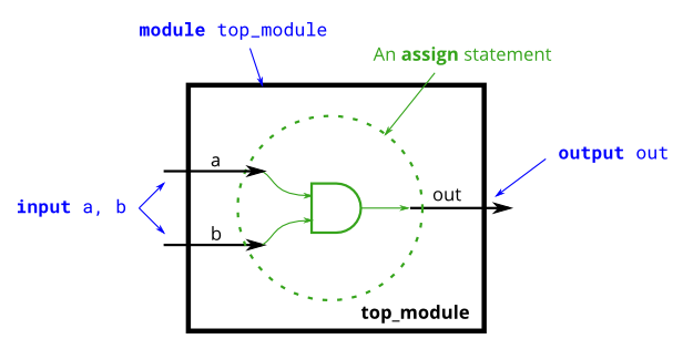
module top_module(
     input a,
     input b,
     output out );
 assign out=a&b;
endmodule
1.5、NOR gate
创建一个实现 NOR 门(或非门)的模块。
module top_module(
     input a,
     input b,
     output out );
     assign out=!(a|b);
endmodule
1.6、XNOR gate
创建一个实现 XNOR 门(异或非门,也就是同或门)的模块。
module top_module(
     input a,
     input b,
     output out );
     assign out=a^~b;
endmodule
1.7、Declaring wires
实现以下电路。
1)创建两条中间线(命名为您想要的任何名称)将 AND 和 OR 门连接在一起。
2)请注意,馈入 NOT 门的线实际上是 wire out,因此您不必在此处声明第三条线。
3)请注意电线是如何由一个源(门的输出)驱动的,但可以馈送多个输入。

 1 module top_module(
 2     input a,
 3     input b,
 4     input c,
 5     input d,
 6     output out,
 7     output out_n   );
 8     wire wire1,wire2;
 9     assign wire1=a&b,wire2=c&d;
10     assign out=wire1|wire2;
11
12     assign out_n=~(wire1|wire2);
13
14 endmodule
1.8、7458 chip
7458 是具有四个与门和两个或门的芯片,创建一个与 7458 芯片功能相同的模块。
1)它有 10 个输入和 2 个输出。您可以选择使用
assign语句来驱动每条输出线,2)或者您可以选择声明(四)条线用作中间信号,其中每条内部线由一个与门的输出驱动。
3)如需额外练习,请尝试两种方式。
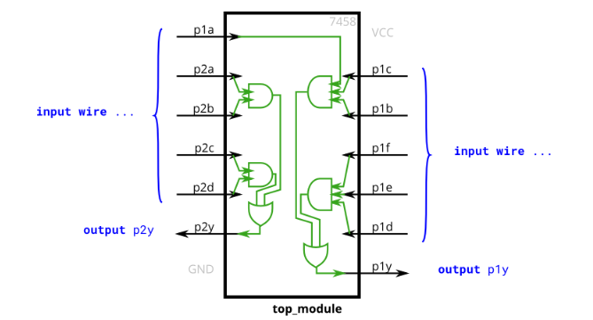
module top_module (
     input p1a, p1b, p1c, p1d, p1e, p1f,
     output p1y,
     input p2a, p2b, p2c, p2d,
     output p2y );
     wire w1,w2,w3,w4;
     assign w1=p2a&p2b,w2=p2c&p2d,w3=p1a&p1c&p1b,w4=p1f&p1e&p1d;
     assign p2y=w1|w2,p1y=w3|w4;
endmodule


【推荐】国内首个AI IDE,深度理解中文开发场景,立即下载体验Trae
【推荐】编程新体验,更懂你的AI,立即体验豆包MarsCode编程助手
【推荐】抖音旗下AI助手豆包,你的智能百科全书,全免费不限次数
【推荐】轻量又高性能的 SSH 工具 IShell:AI 加持,快人一步
· 开源Multi-agent AI智能体框架aevatar.ai,欢迎大家贡献代码
· Manus重磅发布:全球首款通用AI代理技术深度解析与实战指南
· 被坑几百块钱后,我竟然真的恢复了删除的微信聊天记录!
· 没有Manus邀请码?试试免邀请码的MGX或者开源的OpenManus吧
· 园子的第一款AI主题卫衣上架——"HELLO! HOW CAN I ASSIST YOU TODAY