[网络-VLAN]思科LAB-划分不同的VLAN,相同VLAN之间互同,不同VLAN之间不通
LAB 目的:
熟练掌握VLAN操作及原理,实现相同VLAN间能ping通,不同VLAN间无法ping通
网络设备类型:cisco switch

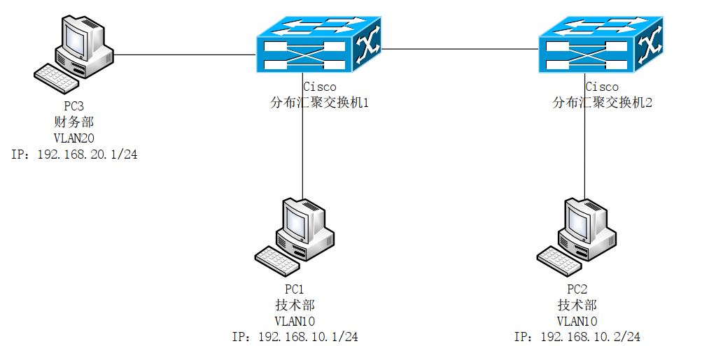
拓扑图:

网络配置信息:

实际应用中的需求:
1)技术部间可以网络互访,技术部与财务部间无法访问
2)只通过二层技术进行不同部门之间网络隔离
3)终端IP地址无网关设置,并配置静态IP地址
具体LAB配置如下:
cisco分布交换机1配置:
 1 Switch>en
 2 Switch#configure
 3 Configuring from terminal, memory, or network [terminal]?
 4 Enter configuration commands, one per line.  End with CNTL/Z.
 5 Switch(config)#vlan 10
 6 Switch(config-vlan)#exit
 7 Switch(config)#vlan 20
 8 Switch(config-vlan)#exit
 9 Switch(config)#interface  fastEthernet 0/1
10 Switch(config-if)#switchport mode access
11 Switch(config-if)#switchport access vlan 10
12 Switch(config-if)#exit
13 Switch(config)#interface  fastEthernet 0/2
14 Switch(config-if)#switchport access vlan 20
15 Switch(config-if)#exit
16 Switch(config)#interface  gigabitEthernet 0/1
17 Switch(config-if)#switchport mode trunk
18 %LINEPROTO-5-UPDOWN: Line protocol on Interface GigabitEthernet0/1, changed state to down
19
20 %LINEPROTO-5-UPDOWN: Line protocol on Interface GigabitEthernet0/1, changed state to up
21
22 Switch(config-if)#switchport trunk allowed vlan 10
23 Switch(config-if)#exit
24 Switch(config)#exit
25 Switch#
26 %SYS-5-CONFIG_I: Configured from console by console
27
28 Switch#write
29 Building configuration...
30 [OK]
cisco分布交换机2配置:
 1 Switch>en
 2 Switch#configure
 3 Configuring from terminal, memory, or network [terminal]?
 4 Enter configuration commands, one per line.  End with CNTL/Z.
 5 Switch(config)#vlan 10
 6 Switch(config-vlan)#exit
 7 Switch(config)#interface fastEthernet 0/1
 8 Switch(config-if)#switchport access vlan 10
 9 Switch(config-if)#exit
10 Switch(config)#interface gigabitEthernet 0/1
11 Switch(config-if)#switchport mode trunk
12 Switch(config-if)#switchport trunk allowed vlan 10
13 Switch(config-if)#end
14 %SYS-5-CONFIG_I: Configured from console by console
15
16 Switch#write
17 Building configuration...
18 [OK]
19 Switch#
20 %LINK-5-CHANGED: Interface FastEthernet0/1, changed state to up
21
22 %LINEPROTO-5-UPDOWN: Line protocol on Interface FastEthernet0/1, changed state to up
技术部PC1访问技术部PC2结果如下:
 1 Packet Tracer PC Command Line 1.0
 2 C:\>ping 192.168.10.2
 3
 4 Pinging 192.168.10.2 with 32 bytes of data:
 5
 6 Reply from 192.168.10.2: bytes=32 time<1ms TTL=128
 7 Reply from 192.168.10.2: bytes=32 time<1ms TTL=128
 8 Reply from 192.168.10.2: bytes=32 time<1ms TTL=128
 9 Reply from 192.168.10.2: bytes=32 time<1ms TTL=128
10
11 Ping statistics for 192.168.10.2:
12     Packets: Sent = 4, Received = 4, Lost = 0 (0% loss),
13 Approximate round trip times in milli-seconds:
14     Minimum = 0ms, Maximum = 0ms, Average = 0ms
技术部PC1访问财务部PC3结果如下:
 1 C:\>ping 192.168.20.1
 2
 3 Pinging 192.168.20.1 with 32 bytes of data:
 4
 5 Request timed out.
 6 Request timed out.
 7 Request timed out.
 8
 9 Ping statistics for 192.168.20.1:
10     Packets: Sent = 4, Received = 0, Lost = 4 (100% loss),
至此实验已完成
此时再看下每个终端获取的MAC地址及IP地址对应关系缓存信息:
技术部PC1:
1 C:\>arp -a                                                   #所含有技术部PC2的MAC地址信息
2   Internet Address      Physical Address      Type
3   192.168.10.2          0001.967d.b74c        dynamic
技术部PC2:
1 C:\>arp -a
2   Internet Address      Physical Address      Type           #所含有技术部PC1的MAC地址信息
3   192.168.10.1          00e0.8f39.152a        dynamic
财务部PC2:
1 C:\>arp -a                 #没有任何MAC地址信息
2 No ARP Entries Found
通过上述实验总结如下:
1)同一vlan可以互访,是在同一个二层广播中,并且通过MAC地址转发数据帧,数据帧封装了上层协议信息(IP地址)
2)二层交换机只工作在数据链路层
本文来自博客园,作者:冰橙阳光,转载请注明原文链接:https://www.cnblogs.com/baktomcat/p/15864277.html
分类:
网络
标签:
网络基础-CCNA级别(初级)


【推荐】国内首个AI IDE,深度理解中文开发场景,立即下载体验Trae
【推荐】编程新体验,更懂你的AI,立即体验豆包MarsCode编程助手
【推荐】抖音旗下AI助手豆包,你的智能百科全书,全免费不限次数
【推荐】轻量又高性能的 SSH 工具 IShell:AI 加持,快人一步
· TypeScript + Deepseek 打造卜卦网站:技术与玄学的结合
· Manus的开源复刻OpenManus初探
· AI 智能体引爆开源社区「GitHub 热点速览」
· 从HTTP原因短语缺失研究HTTP/2和HTTP/3的设计差异
· 三行代码完成国际化适配,妙~啊~