
Cisco基础(五):配置静态NAT、配置端口映射、配置动态NAT、PAT配置、办公区Internet的访问
一、配置静态NAT
目标:
随着接入Internet的计算机数量的不断猛增,IP地址资源也就愈加显得捉襟见肘。事实上,除了中国教育和科研计算机网(CERNET)外,一般用户几乎申请不到整段的C类IP地址。在其他ISP那里,即使是拥有几百台计算机的大型局域网用户,当他们申请IP地址时,所分配的地址也不过只有几个或十几个IP地址。显然,这样少的IP地址根本无法满足网络用户的需求。
- 在R1上配置静态NAT使192.168.1.1转换为61.159.62.131,192.168.1.2转换为61.159.62.132,实现外部网络访问。
方案:
借助于NAT,私有(保留)地址的"内部"网络通过路由器发送数据包时,私有地址被转换成合法的IP地址,一个局域网只需使用少量IP地址(甚至是1个)即可实现私有地址网络内所有计算机与Internet的通信需求。
这种通过使用少量的公有IP 地址代表较多的私有IP 地址的方式,将有助于减缓可用IP地址空间的枯竭。而且还能够有效地避免来自网络外部的攻击,隐藏并保护网络内部的计算机。
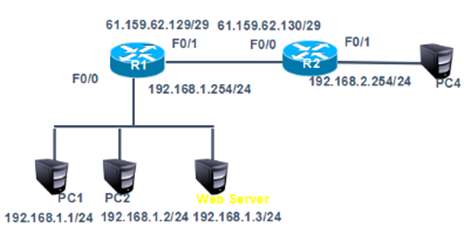
网络拓扑如下图所示:

步骤:
步骤一:通用配置
1)配置R1端口IP地址,以及默认路由
tarena-R1(config)#interface f0/0
tarena-R1(config-if)#ip address 192.168.1.254 255.255.255.0
tarena-R1(config-if)#no shutdown
tarena-R1(config-if)#interface f0/1
tarena-R1(config-if)#ip address 61.159.62.129 255.255.255.248
tarena-R1(config-if)#no shutdown
tarena-R1(config-if)#exit
tarena-R1(config)#ip route 0.0.0.0 0.0.0.0 f0/1
2)配置R2端口IP地址
不需要在R2上配置到企业内网的静态路由,因为NAT的存在,企业内部的地址都将被转换、隐藏。
tarena-R2(config)#interface f0/0
tarena-R2(config-if)#ip address 61.159.62.130 255.255.255.248
tarena-R2(config-if)#no shutdown
tarena-R2(config-if)#interface f0/1
tarena-R2(config-if)#ip address 192.168.2.254 255.255.255.0
tarena-R2(config-if)#no shutdown
步骤二:静态NAT配置
1)在R1上将192.168.1.1映射到61.159.62.131,将192.168.1.2映射到61.159.62.132
静态映射有唯一对应的关系。
通过静态NAT,可以把内网服务器发布到外网。
tarena-R1(config)#ip nat inside source static 192.168.1.1 61.159.62.131
tarena-R1(config)#ip nat inside source static 192.168.1.2 61.159.62.132
2)在R1上配置NAT内、外端口
tarena-R1(config)#interface f0/0
tarena-R1(config-if)#ip nat inside
tarena-R1(config-if)#interface f0/1
tarena-R1(config-if)#ip nat outside
3)分别在两台PC机上测试到外网主机的通信
PC1测试如下所示:
PC>ipconfig
FastEthernet0 Connection:(default port)
Link-local IPv6 Address.........: FE80::2D0:FFFF:FE45:CACC
IP Address......................: 192.168.1.1
Subnet Mask.....................: 255.255.255.0
Default Gateway.................: 192.168.1.254
PC>ping 192.168.2.1
Pinging 192.168.2.1 with 32 bytes of data:
Reply from 192.168.2.1: bytes=32 time=1ms TTL=126
Reply from 192.168.2.1: bytes=32 time=0ms TTL=126
Reply from 192.168.2.1: bytes=32 time=0ms TTL=126
Reply from 192.168.2.1: bytes=32 time=0ms TTL=126
Ping statistics for 192.168.2.1:
Packets: Sent = 4, Received = 4, Lost = 0 (0% loss),
Approximate round trip times in milli-seconds:
Minimum = 0ms, Maximum = 1ms, Average = 0ms
PC>
PC2的测试如下所示:
PC>ipconfig
FastEthernet0 Connection:(default port)
Link-local IPv6 Address.........: FE80::200:CFF:FEEA:DE30
IP Address......................: 192.168.1.2
Subnet Mask.....................: 255.255.255.0
Default Gateway.................: 192.168.1.254
PC>ping 192.168.2.1
Pinging 192.168.2.1 with 32 bytes of data:
Request timed out.
Reply from 192.168.2.1: bytes=32 time=0ms TTL=126
Reply from 192.168.2.1: bytes=32 time=0ms TTL=126
Reply from 192.168.2.1: bytes=32 time=0ms TTL=126
Ping statistics for 192.168.2.1:
Packets: Sent = 4, Received = 3, Lost = 1 (25% loss),
Approximate round trip times in milli-seconds:
Minimum = 0ms, Maximum = 0ms, Average = 0ms
PC>
4)在R1上查看NAT转换表
tarena-R1#show ip nat translations
Pro Inside global Inside local Outside local Outside global
icmp 61.159.62.131:10 192.168.1.1:10 192.168.2.1:10 192.168.2.1:10
icmp 61.159.62.131:11 192.168.1.1:11 192.168.2.1:11 192.168.2.1:11
icmp 61.159.62.131:12 192.168.1.1:12 192.168.2.1:12 192.168.2.1:12
icmp 61.159.62.131:9 192.168.1.1:9 192.168.2.1:9 192.168.2.1:9
icmp 61.159.62.132:27 192.168.1.2:27 192.168.2.1:27 192.168.2.1:27
icmp 61.159.62.132:28 192.168.1.2:28 192.168.2.1:28 192.168.2.1:28
icmp 61.159.62.132:29 192.168.1.2:29 192.168.2.1:29 192.168.2.1:29
icmp 61.159.62.132:30 192.168.1.2:30 192.168.2.1:30 192.168.2.1:30
二、配置端口映射
目标:
通过端口映射技术将内部服务器发布向Internet。
方案:
在R1上配置端口映射将192.168.1.3的80端口映射为61.159.62.133的80端口,将web服务器发布到Internet。网络拓扑如下图所示:
步骤:
步骤一:通用配置
1)在案例一基础上取消静态转换条目,在192.168.1.0网络新增一台web服务器IP为192.168.1.3。将192.168.1.3的80端口映射为61.159.62.133的80端口
tarena-R1(config)#no ip nat inside source static 192.168.1.1 61.159.62.131
tarena-R1(config)#no ip nat inside source static 192.168.1.2 61.159.62.132
tarena-R1 (config)#ip nat inside source static tcp 192.168.1.3 80 61.159.62.133 80
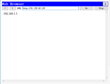
步骤二:PC3上访问web服务器进行验证
1)外部主机PC4上访问61.159.62.133进行验证,如下图所示
三、配置动态NAT
目标:
在R1通过动态NAT实现企业内网192.168.1.0/24转换为公网地址61.159.62.131-61.159.62.134,访问192.168.2.1
方案:
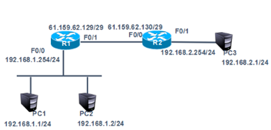
网络拓扑如下图所示:
步骤:
步骤一:动态NAT配置
1)删除案例2中的端口映射
tarena-R1 (config)#no ip nat inside source static tcp 192.168.1.3 80 61.159.62.133 80
2)在R1上配置ACL
tarena-R1(config)#access-list 1 permit 192.168.1.0 0.0.0.255
3)在R1上配置可转换的公网IP地址池
地址池是向ISP(Internet服务提供商,如电信、联通)申请得到的,内网主机(上一步ACL中所包含的IP地址)到外网的访问,内网地址将被动态的、随机的转换为这些合法地址。
tarena-R1(config)#ip nat pool natpool 61.159.62.131 61.159.62.134 netmask 255.255.255.248
4)关联ACL和公网的IP地址池
tarena-R1(config)#ip nat inside source list 1 pool natpool
5)在R1上配置NAT内、外端口
tarena-R1(config)#interface f0/0
tarena-R1(config-if)#ip nat inside
tarena-R1(config-if)#interface f0/1
tarena-R1(config-if)#ip nat outside
6)分别在两台PC机上测试到外网主机的通信
PC1测试如下所示:
PC>ipconfig
FastEthernet0 Connection:(default port)
Link-local IPv6 Address.........: FE80::2D0:FFFF:FE45:CACC
IP Address......................: 192.168.1.1
Subnet Mask.....................: 255.255.255.0
Default Gateway.................: 192.168.1.254
PC>ping 192.168.2.1
Pinging 192.168.2.1 with 32 bytes of data:
Reply from 192.168.2.1: bytes=32 time=1ms TTL=126
Reply from 192.168.2.1: bytes=32 time=0ms TTL=126
Reply from 192.168.2.1: bytes=32 time=0ms TTL=126
Reply from 192.168.2.1: bytes=32 time=0ms TTL=126
Ping statistics for 192.168.2.1:
Packets: Sent = 4, Received = 4, Lost = 0 (0% loss),
Approximate round trip times in milli-seconds:
Minimum = 0ms, Maximum = 1ms, Average = 0ms
PC>
PC2测试如下所示:
PC>ipconfig
FastEthernet0 Connection:(default port)
Link-local IPv6 Address.........: FE80::2D0:FFFF:FE45:CACC
IP Address......................: 192.168.1.2
Subnet Mask.....................: 255.255.255.0
Default Gateway.................: 192.168.1.254
PC>ping 192.168.2.1
Pinging 192.168.2.1 with 32 bytes of data:
Reply from 192.168.2.1: bytes=32 time=1ms TTL=126
Reply from 192.168.2.1: bytes=32 time=0ms TTL=126
Reply from 192.168.2.1: bytes=32 time=0ms TTL=126
Reply from 192.168.2.1: bytes=32 time=0ms TTL=126
Ping statistics for 192.168.2.1:
Packets: Sent = 4, Received = 4, Lost = 0 (0% loss),
Approximate round trip times in milli-seconds:
Minimum = 0ms, Maximum = 1ms, Average = 0ms
7)在R1上查看NAT转换表
转换表中的对应关系是动态的,如192.168.1.1被转换为61.159.62.131,但是下一次对外网的访问很有可能被转换为其他地址。
tarena-R1#show ip nat translations
Pro Inside global Inside local Outside local Outside global
icmp 61.159.62.131:1362192.168.1.1:1362 192.168.2.1:1362 192.168.2.1:1362
icmp 61.159.62.131:1392192.168.1.1:1392 192.168.2.1:1392 192.168.2.1:1392
icmp 61.159.62.131:1393192.168.1.1:1393 192.168.2.1:1393 192.168.2.1:1393
icmp 61.159.62.131:1394192.168.1.1:1394 192.168.2.1:1394 192.168.2.1:1394
icmp 61.159.62.132:13 192.168.1.2:13 192.168.2.1:13 192.168.2.1:13
icmp 61.159.62.132:14 192.168.1.2:14 192.168.2.1:14 192.168.2.1:14
icmp 61.159.62.132:15 192.168.1.2:15 192.168.2.1:15 192.168.2.1:15
icmp 61.159.62.132:16 192.168.1.2:16 192.168.2.1:16 192.168.2.1:16
四、PAT配置
目标:
在R1配置PAT端口多路复用使企业内网192.168.1.0/24复用f0/1端口的IP,实现外部网络的访问。
方案:
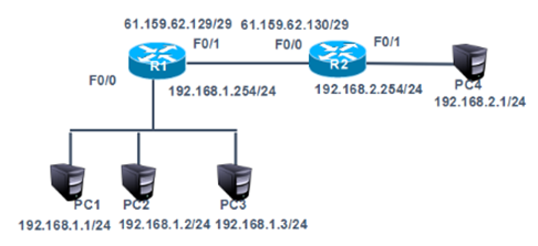
网络拓扑如下图所示:
步骤:
步骤一:基于端口的PAT配置限制
1)删除案例3中动态NAT配置
tarena-R1(config)#no ip nat inside source list 1
tarena-R1(config)#no ip nat pool natpool
tarena-R1(config)#no access-list 1
2)在R1上配置ACL
tarena-R1(config)#access-list 1 permit 192.168.1.0 0.0.0.255
3)关联ACL和路由器连接互联网的端口
该命令最后加上的overload表示复用。
tarena-R1(config)#ip nat inside source list 1 interface f0/1 overload
4)在R1上配置NAT内、外端口
tarena-R1(config)#interface f0/0
tarena-R1(config-if)#ip nat inside
tarena-R1(config-if)#interface f0/1
tarena-R1(config-if)#ip nat outside
5)分别在两台PC机上测试到外网主机的通信
PC1测试如下所示:
PC>ipconfig
FastEthernet0 Connection:(default port)
Link-local IPv6 Address.........: FE80::2D0:FFFF:FE45:CACC
IP Address......................: 192.168.1.1
Subnet Mask.....................: 255.255.255.0
Default Gateway.................: 192.168.1.254
PC>ping 192.168.2.1
Pinging 192.168.2.1 with 32 bytes of data:
Reply from 192.168.2.1: bytes=32 time=1ms TTL=126
Reply from 192.168.2.1: bytes=32 time=0ms TTL=126
Reply from 192.168.2.1: bytes=32 time=0ms TTL=126
Reply from 192.168.2.1: bytes=32 time=0ms TTL=126
Ping statistics for 192.168.2.1:
Packets: Sent = 4, Received = 4, Lost = 0 (0% loss),
Approximate round trip times in milli-seconds:
Minimum = 0ms, Maximum = 1ms, Average = 0ms
PC>
PC2测试如下所示:
PC>ipconfig
FastEthernet0 Connection:(default port)
Link-local IPv6 Address.........: FE80::2D0:FFFF:FE45:CACC
IP Address......................: 192.168.1.2
Subnet Mask.....................: 255.255.255.0
Default Gateway.................: 192.168.1.254
PC>ping 192.168.2.1
Pinging 192.168.2.1 with 32 bytes of data:
Reply from 192.168.2.1: bytes=32 time=1ms TTL=126
Reply from 192.168.2.1: bytes=32 time=0ms TTL=126
Reply from 192.168.2.1: bytes=32 time=0ms TTL=126
Reply from 192.168.2.1: bytes=32 time=0ms TTL=126
Ping statistics for 192.168.2.1:
Packets: Sent = 4, Received = 4, Lost = 0 (0% loss),
Approximate round trip times in milli-seconds:
Minimum = 0ms, Maximum = 1ms, Average = 0ms
PC>
6)在R1上查看NAT转换表
tarena-R1#show ip nat translations
Pro Inside global Inside local Outside local Outside global
icmp 61.159.62.129:2029192.168.1.1:2029 192.168.2.1:2029 192.168.2.1:2029
icmp 61.159.62.129:2030192.168.1.1:2030 192.168.2.1:2030 192.168.2.1:2030
icmp 61.159.62.129:2031192.168.1.1:2031 192.168.2.1:2031 192.168.2.1:2031
icmp 61.159.62.129:2032192.168.1.1:2032 192.168.2.1:2032 192.168.2.1:2032
icmp 61.159.62.129:2033192.168.1.1:2033 192.168.2.1:2033 192.168.2.1:2033
icmp 61.159.62.129:2034192.168.1.1:2034 192.168.2.1:2034 192.168.2.1:2034
icmp 61.159.62.129:2035192.168.1.1:2035 192.168.2.1:2035 192.168.2.1:2035
输出结果显示,所有的内网IP地址在访问外网前均被转换成了路由器端口的IP地址。
五、办公区Internet的访问
目标:
在R1配置PAT端口多路复用使企业内网192.168.1.0/24复用f0/1端口的IP,实现外部网络的访问。
方案:
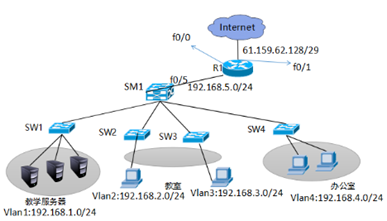
网络拓扑如下图所示:
步骤:
步骤一:在SM1划分vlan2、vlan3、vlan4 并给SM1配置虚端口IP并开启路由功能,1-4接口开启trunk
1)创建vlan并设置管理IP,开启路由功能,并把相应的接口划分到vlan下
SM1 (config)ip routing
SM1 (config)#vlan 2
SM1 (config-vlan)#vlan 3
SM1 (config-vlan)#vlan 4
SM1 (config-vlan)#
SM1 (config-vlan)#exit
SM1 (config)#interface vlan 1
SM1 (config-if)#ip address 192.168.1.254 255.255.255.0
SM1 (config-if)#eixt
SM1 (config-if)#no shutdown
SM1 (config-if)#exit
SM1 (config)#interface vlan 2
SM1 (config-if)#ip address 192.168.2.254 255.255.255.0
SM1 (config-if)#no shutdown
SM1 (config-if)#exit
SM1 (config)#interface vlan 3
SM1 (config-if)#ip address 192.168.3.254 255.255.255.0
SM1 (config-if)#no shutdown
SM1 (config-if)#exit
SM1 (config)#interface vlan 4
SM1 (config-if)#ip address 192.168.4.254 255.255.255.0
SM1 (config-if)#no shutdown
sw2(config)#vlan 2
sw2(config-vlan)#exit
sw2(config)#interface fastEthernet 0/1
sw2(config-if)#switchport access vlan 2
sw3(config)#vlan 3
sw3(config-vlan)#exit
sw3(config)#interface fastEthernet 0/1
sw3(config-if)#switchport access vlan 3
sw4(config)#vlan 4
sw4(config-vlan)#exit
sw4(config)#interface fastEthernet 0/1
sw4(config-if)#switchport access vlan 4
2)交换机之间所连接的接口开启trunk
SM1(config)#interface range f0/1 - 4
SM1 (config-if-range)#switchport trunk encapsulation dot1q
SM1 (config-if-range)#switchport mode trunk
sw1(config)#interface fastEthernet 0/3
sw1(config-if)#switchport mode trunk
sw2(config)#interface fastEthernet 0/3
sw2(config-if)#switchport mode trunk
sw3(config)#interface fastEthernet 0/3
sw3(config-if)#switchport mode trunk
sw4(config)#interface fastEthernet 0/3
sw4(config-if)#switchport mode trunk
3)测试vlan之间的连通性
PC>ipconfig
FastEthernet0 Connection:(default port)
Link-local IPv6 Address.........: FE80::290:21FF:FEC2:1A50
IP Address......................: 192.168.1.1
Subnet Mask.....................: 255.255.255.0
Default Gateway.................: 192.168.1.254
PC>ping 192.168.2.1
Pinging 192.168.2.1 with 32 bytes of data:
Reply from 192.168.2.1: bytes=32 time=0ms TTL=127
Reply from 192.168.2.1: bytes=32 time=0ms TTL=127
Reply from 192.168.2.1: bytes=32 time=0ms TTL=127
Reply from 192.168.2.1: bytes=32 time=1ms TTL=12
Ping statistics for 192.168.2.1:
Packets: Sent = 4, Received = 3, Lost = 1 (25% loss),
Approximate round trip times in milli-seconds:
Minimum = 0ms, Maximum = 1ms, Average = 0ms
PC>ping 192.168.3.1
Pinging 192.168.3.1 with 32 bytes of data:
Reply from 192.168.2.1: bytes=32 time=0ms TTL=127
Reply from 192.168.3.1: bytes=32 time=0ms TTL=127
Reply from 192.168.3.1: bytes=32 time=0ms TTL=127
Reply from 192.168.3.1: bytes=32 time=1ms TTL=127
Ping statistics for 192.168.3.1:
Packets: Sent = 4, Received = 3, Lost = 1 (25% loss),
Approximate round trip times in milli-seconds:
Minimum = 0ms, Maximum = 1ms, Average = 0ms
PC>ping 192.168.4.1
Pinging 192.168.4.1 with 32 bytes of data:
Reply from 192.168.2.1: bytes=32 time=0ms TTL=127
Reply from 192.168.2.1: bytes=32 time=0ms TTL=127
Reply from 192.168.2.1: bytes=32 time=0ms TTL=127
Reply from 192.168.4.1: bytes=32 time=0ms TTL=127
Ping statistics for 192.168.4.1:
Packets: Sent = 4, Received = 1, Lost = 3 (75% loss),
Approximate round trip times in milli-seconds:
Minimum = 0ms, Maximum = 0ms, Average = 0ms
4)为SM1与路由器连接的接口和路由器配置IP并启用动态路由RIP协议.
SM1(config)#interface fastEthernet 0/5
SM1(config-if)#no switchport
SM1(config-if)#ip add 192.168.5.1 255.255.255.0
SM1(config-if)#no shutdown
SM1(config-if)#exit
SM1(config)#router rip
SM1(config-router)#version 2
SM1(config-router)#no auto-summary
SM1(config-router)#network 192.168.1.0
SM1(config-router)#network 192.168.2.0
SM1(config-router)#network 192.168.3.0
SM1(config-router)#network 192.168.4.0
SM1(config-router)#network 192.168.5.0
Router(config)#interface fastEthernet 0/0
Router(config-if)#ip address 192.168.5.2 255.255.255.0
Router(config-if)#no shutdown
Router(config-if)#exit
Router(config)#interface fastEthernet 0/1
Router(config-if)#ip address 61.159.62.129 255.255.255.248
Router(config-if)#exit
Router(config)#router rip
Router(config-router)#version 2
Router(config-router)#no auto-summary
Router(config-router)#network 192.168.5.0
5)在路由器上配置默认路由并发布到RIP协议里并在三成交换机SM1上查看路由表
Router(config)#ip route 0.0.0.0 0.0.0.0 f0/1
Router(config)#router rip
Router(config-router)#default-information originate
SM路由表如下所示:
SM1# show ip route
Codes: C - connected, S - static, I - IGRP, R - RIP, M - mobile, B - BGP
D - EIGRP, EX - EIGRP external, O - OSPF, IA - OSPF inter area
N1 - OSPF NSSA external type 1, N2 - OSPF NSSA external type 2
E1 - OSPF external type 1, E2 - OSPF external type 2, E - EGP
i - IS-IS, L1 - IS-IS level-1, L2 - IS-IS level-2, ia - IS-IS inter area
* - candidate default, U - per-user static route, o - ODR
P - periodic downloaded static route
Gateway of last resort is 192.168.5.2 to network 0.0.0.0
C 192.168.1.0/24 is directly connected, Vlan1
C 192.168.2.0/24 is directly connected, Vlan2
C 192.168.3.0/24 is directly connected, Vlan3
C 192.168.4.0/24 is directly connected, Vlan4
C 192.168.5.0/24 is directly connected, FastEthernet0/5
R* 0.0.0.0/0 [120/1] via 192.168.5.2, 00:00:18, FastEthernet0/5
6)在路由器上配置PAT
Router(config)#access-list 1 permit 192.168.4.0 0.0.0.255
Router(config)#ip nat inside source list 1 interface f0/1
Router(config)#interface fastEthernet 0/0
Router(config-if)#ip nat inside
Router(config-if)#exit
Router(config)#interface fastEthernet 0/1
Router(config-if)#ip nat outside
7)用192.168.4.0和192.168.1.0测试网络连通性
PC1
PC>ping 61.159.62.130
Pinging 61.159.62.130 with 32 bytes of data:
Request timed out.
Request timed out.
Request timed out.
Request timed out.
Ping statistics for 61.159.62.130:
Packets: Sent = 4, Received = 0, Lost = 4 (100% loss),
PC4
PC>ping 61.159.62.130
Pinging 61.159.62.130 with 32 bytes of data:
Reply from 61.159.62.130: bytes=32 time=0ms TTL=126
Reply from 61.159.62.130: bytes=32 time=0ms TTL=126
Reply from 61.159.62.130: bytes=32 time=0ms TTL=126
Reply from 61.159.62.130: bytes=32 time=0ms TTL=126
Ping statistics for 61.159.62.130:
Packets: Sent = 4, Received = 4, Lost = 0 (0% loss),
Approximate round trip times in milli-seconds:
Minimum = 0ms, Maximum = 0ms, Average = 0ms
结果显示只有办公网可以访问Internet

 浙公网安备 33010602011771号