Linux IIO子系统概述(结合STM32 ADC/DAC驱动)
关键词:IIO、ADC、DAC、Trigger等等。
IIO(Industrial I/O)主要用于数字量和模拟量转换的IO接口设备。这些设备种类繁多,内部一般都会有一个ADC或者DAC。SOC对这些设备操作可以通过I2C/SPI,或者直接访问寄存器进行。
IIO子系统主要管理抽象这些类别设备:
- 模数转换器(ADC)
- 加速度计(Accelerometers)
- 陀螺仪(Gyros)
- 惯性测量单元 IMUs)
- 电容数字转换器 (CDC)
- 压力传感器
- 颜色、光线和接近传感器
- 温度传感器
- 磁力计(Magnetometers)
- 数模转换器(DAC)
- 直接数字合成器(DDS)
- 锁相环(PLL)
- 可变/可编程增益放大器(VGA、PGA)
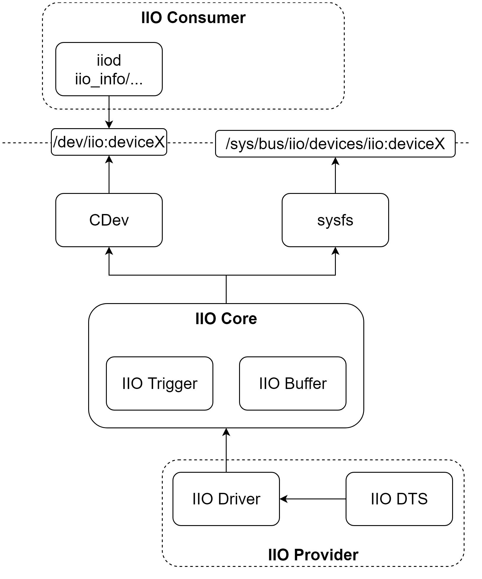
Linux下IIO框架可以分为如下几部分:
- IIO Core提供IIO设备、IIO Trigger、IIO Buffer分配、初始化、注册等工作。
- IIO Driver不同IIO设备的驱动程序。
- IIO sysfs对用户空间提供IIO设备访问和配置。

1 IIO子系统配置
Device Drivers
  Industrial I/O support
    Enable buffer support within IIO
      IIO callback buffer used for push in-kernel interfaces
      Industrial I/O HW buffering
      Industrial I/O buffering based on kfifo
    Enable IIO configuration via configfs
    Enable triggered sampling support
      Maximum number of consumers per trigger
    Enable software IIO device support
    Enable software triggers support
    Analog to digital converters
    Digital to analog converters
    Temperature sensors
涉及到文件有:
drivers/iio/
├── adc
│   ├── stm32-adc.c--ADC传感器特定通道驱动。
│   ├── stm32-adc-core.c--ADC传感器驱动。
├── buffer
│   ├── industrialio-buffer-cb.c
│   ├── industrialio-hw-consumer.c
│   ├── industrialio-triggered-buffer.c
│   ├── kfifo_buf.c
├── dac
│   ├── stm32-dac.c--DAC传感器特定通道驱动。
│   ├── stm32-dac-core.c--DAC传感器驱动。
├── industrialio-buffer.c
├── industrialio-configfs.c
├── industrialio-core.c
├── industrialio-event.c
├── industrialio-sw-device.c
├── industrialio-triggered-event.c
├── inkern.c
└── trigger
   ├── iio-trig-hrtimer.c
   ├── iio-trig-interrupt.c
   ├── iio-trig-sysfs.c
   └── stm32-timer-trigger.c
2 IIO Core
2.1 IIO数据结构
2.1.1 IIO Device
struct iio_dev用于描述一个具体IIO设备,更多参考《Core elements — iio_dev》。
struct iio_dev {
    int                id;
    struct module            *driver_module;

    int                modes;--表示设备支持的模式:
    int                currentmode;--表示设备当前模式。
#define INDIO_DIRECT_MODE        0x01--提供sysfs接口,直接读取。
#define INDIO_BUFFER_TRIGGERED        0x02-
#define INDIO_BUFFER_SOFTWARE        0x04
#define INDIO_BUFFER_HARDWARE        0x08
#define INDIO_EVENT_TRIGGERED        0x10--支持事件触发。
#define INDIO_HARDWARE_TRIGGERED    0x20-支持硬件中断触发。

#define INDIO_ALL_BUFFER_MODES                    \
    (INDIO_BUFFER_TRIGGERED | INDIO_BUFFER_HARDWARE | INDIO_BUFFER_SOFTWARE)

#define INDIO_ALL_TRIGGERED_MODES    \
    (INDIO_BUFFER_TRIGGERED        \
     | INDIO_EVENT_TRIGGERED    \
     | INDIO_HARDWARE_TRIGGERED)
struct device            dev;

    struct iio_event_interface    *event_interface;

    struct iio_buffer        *buffer;
    struct list_head        buffer_list;
    int                scan_bytes;
    struct mutex            mlock;

    const unsigned long        *available_scan_masks;
    unsigned            masklength;
    const unsigned long        *active_scan_mask;
    bool                scan_timestamp;
    unsigned            scan_index_timestamp;
    struct iio_trigger        *trig;
    bool                trig_readonly;
    struct iio_poll_func        *pollfunc;
    struct iio_poll_func        *pollfunc_event;

    struct iio_chan_spec const    *channels;--IIO设备通道列表。
    int                num_channels;--IIO设备通道数。

    struct list_head        channel_attr_list;
    struct attribute_group        chan_attr_group;
    const char            *name;
    const struct iio_info        *info;
    clockid_t            clock_id;
    struct mutex            info_exist_lock;
    const struct iio_buffer_setup_ops    *setup_ops;
    struct cdev            chrdev;
#define IIO_MAX_GROUPS 6
    const struct attribute_group    *groups[IIO_MAX_GROUPS + 1];
    int                groupcounter;

    unsigned long            flags;
#if defined(CONFIG_DEBUG_FS)
    struct dentry            *debugfs_dentry;
    unsigned            cached_reg_addr;
#endif
};
struct iio_info包含每个iio设备的属性和具体实现函数。更多参考《Core elements — iio_info》。
struct iio_info {
    const struct attribute_group    *event_attrs;
    const struct attribute_group    *attrs;

    int (*read_raw)(struct iio_dev *indio_dev,
int (*read_raw_multi)(struct iio_dev *indio_dev,
int (*read_avail)(struct iio_dev *indio_dev,
int (*write_raw)(struct iio_dev *indio_dev,
 int (*write_raw_get_fmt)(struct iio_dev *indio_dev,
int (*read_event_config)(struct iio_dev *indio_dev,
int (*write_event_config)(struct iio_dev *indio_dev,
int (*read_event_value)(struct iio_dev *indio_dev,
int (*write_event_value)(struct iio_dev *indio_dev,
int (*validate_trigger)(struct iio_dev *indio_dev,
int (*update_scan_mode)(struct iio_dev *indio_dev,
int (*debugfs_reg_access)(struct iio_dev *indio_dev,
int (*of_xlate)(struct iio_dev *indio_dev,
int (*hwfifo_set_watermark)(struct iio_dev *indio_dev, unsigned val);
    int (*hwfifo_flush_to_buffer)(struct iio_dev *indio_dev,
};
一个IIO设备可能有多个通道,每个通道由struct iio_chan_spec表示。更多参考《Core elements — iio_chan_spec》。
struct iio_chan_spec {
    enum iio_chan_type    type;--表示channel类型,电压、电流、加速度、电磁等等。
    int            channel;
    int            channel2;
    unsigned long        address;
    int            scan_index;
    struct {
        char    sign;
        u8    realbits;
        u8    storagebits;
        u8    shift;
        u8    repeat;
        enum iio_endian endianness;
    } scan_type;
    long            info_mask_separate;
    long            info_mask_separate_available;
    long            info_mask_shared_by_type;
    long            info_mask_shared_by_type_available;
    long            info_mask_shared_by_dir;
    long            info_mask_shared_by_dir_available;
    long            info_mask_shared_by_all;
    long            info_mask_shared_by_all_available;
    const struct iio_event_spec *event_spec;
    unsigned int        num_event_specs;
    const struct iio_chan_spec_ext_info *ext_info;
    const char        *extend_name;
    const char        *datasheet_name;
    unsigned        modified:1;
    unsigned        indexed:1;
    unsigned        output:1;
    unsigned        differential:1;
};
2.1.2 IIO Trigger
触发器是基于某种信号来触发数据采集,比如:数据就绪中断;周期性中断;用户空间sysfs读写。关于Trigger更多参考《Triggers — The Linux Kernel documentation》。
struct iio_trigger {
    const struct iio_trigger_ops    *ops;
    struct module            *owner;
    int                id;
    const char            *name;
    struct device            dev;

    struct list_head        list;
    struct list_head        alloc_list;
    atomic_t            use_count;

    struct irq_chip            subirq_chip;
    int                subirq_base;

    struct iio_subirq subirqs[CONFIG_IIO_CONSUMERS_PER_TRIGGER];
    unsigned long pool[BITS_TO_LONGS(CONFIG_IIO_CONSUMERS_PER_TRIGGER)];
    struct mutex            pool_lock;
    bool                attached_own_device;
};
struct iio_trigger_ops是一个触发器的操作函数集,包括:
struct iio_trigger_ops {
    int (*set_trigger_state)(struct iio_trigger *trig, bool state);--设置触发器状态,打开或关闭。
    int (*try_reenable)(struct iio_trigger *trig);--当用户计数为0时,重新使能接口。
    int (*validate_device)(struct iio_trigger *trig,
                   struct iio_dev *indio_dev);
};
2.1.3 IIO Buffer
IIO缓冲区用于保存采集到的数据。关于Buffer更多参考《Buffers — The Linux Kernel documentation》。
struct iio_buffer {
    unsigned int length;
    size_t bytes_per_datum;
    const struct iio_buffer_access_funcs *access;
    long *scan_mask;
    struct list_head demux_list;
    wait_queue_head_t pollq;
    unsigned int watermark;
};
2.2 IIO Core初始化
IIO子系统初始化包括:
- iio总线注册。
- 分配IIO字符设备号。
- 创建IIO设备debugfs。
iio_init
  ->bus_register--注册iio bus。
  ->alloc_chrdev_region--创建iio cdev设备编号iio_devt。
  ->debugfs_create_dir--创建/sys/kernel/debug/iio调试目录iio_debugfs_dentry。
2.3 IIO Core API
2.3.1 IIO设备分配注册
IIO设备分配和释放函数如下:
struct iio_dev *iio_device_alloc(int sizeof_priv);void iio_device_free(struct iio_dev *indio_dev);
int devm_iio_device_match(struct device *dev, void *res, void *data);
struct iio_dev *devm_iio_device_alloc(struct device *dev, int sizeof_priv);
void devm_iio_device_free(struct device *dev, struct iio_dev *indio_dev);
IIO设备注册和注销函数如下:
#define iio_device_register(indio_dev) \
    __iio_device_register((indio_dev), THIS_MODULE)
int __iio_device_register(struct iio_dev *indio_dev, struct module *this_mod);
void iio_device_unregister(struct iio_dev *indio_dev);
#define devm_iio_device_register(dev, indio_dev) \
    __devm_iio_device_register((dev), (indio_dev), THIS_MODULE);
int __devm_iio_device_register(struct device *dev, struct iio_dev *indio_dev,
                   struct module *this_mod);
void devm_iio_device_unregister(struct device *dev, struct iio_dev *indio_dev);
devm_iio_device_register/iio_device_register向IIO子系统注册一个IIO设备。
devm_iio_device_register/iio_device_register
  ->__iio_device_register
    ->iio_check_unique_scan_index
    ->iio_device_register_debugfs
      ->debugfs_create_file--创建direct_reg_access调试节点,通过此节点可以直接读写寄存器。iio_debugfs_reg_fops调用IIO设备struct iio_dev->info->debugfs_reg_access()函数。
    ->iio_buffer_alloc_sysfs_and_mask
    ->iio_device_register_sysfs--创建adc属性和每个channel属性。
    ->iio_device_register_eventset
    ->iio_device_register_trigger_consumer
    ->cdev_init--初始化cdev设备,操作函数集为iio_buffer_fileops。
    ->cdev_device_add--创建cdev设备/dev/iio:deviceX。
IIO字符设备的操作函数iio_buffer_fileops:
static const struct file_operations iio_buffer_fileops = {
    .read = iio_buffer_read_first_n_outer_addr,
    .release = iio_chrdev_release,
    .open = iio_chrdev_open,
    .poll = iio_buffer_poll_addr,
    .owner = THIS_MODULE,
    .llseek = noop_llseek,
    .unlocked_ioctl = iio_ioctl,
    .compat_ioctl = iio_ioctl,
};
iio_chrdev_open()/iio_chrdev_release()对文件的打开关闭通过对设备增加减少引用计数。
iio_chrdev_open
  ->iio_device_get
iio_chrdev_release
  ->iio_device_put
iio_ioctl()函数创建一个匿名文件,并返回句柄。
iio_ioctl--仅支持IIO_GET_EVENT_FD_IOCTL命令。
  iio_event_getfd
    iio_device_get
    anon_inode_getfd--创建一个匿名文件,操作函数集为iio_event_chrdev_fileops。
在定义CONFIG_IIO_BUFFER时,iio_buffer_poll_addr即为iio_buffer_poll:
iio_buffer_poll
  poll_wait--等待buffer就绪,被wake_up。
  iio_buffer_ready--判断buffer是否就绪,就绪则返回EPOLLIN | EPOLLRDNORM;否则返回0。
iio_buffer_read_first_n_outer_add()为从buffer中读取数据接口,对应iio_buffer_read_first_n_outer()函数:
iio_buffer_read_first_n_outer
  add_wait_queue
  iio_buffer_ready
  wait_woken
2.3.1 IIO Trigger和Buffer
IIO trigrer的分配和释放如下:
struct iio_trigger *devm_iio_trigger_alloc(struct device *dev,
                        const char *fmt, ...);
void devm_iio_trigger_free(struct device *dev, struct iio_trigger *iio_trig);
IIO trigger的注册和注销函数如下:
#define iio_trigger_register(trig_info) \
    __iio_trigger_register((trig_info), THIS_MODULE)
int __iio_trigger_register(struct iio_trigger *trig_info,
               struct module *this_mod);

#define devm_iio_trigger_register(dev, trig_info) \
    __devm_iio_trigger_register((dev), (trig_info), THIS_MODULE)
int __devm_iio_trigger_register(struct device *dev,
                struct iio_trigger *trig_info,
                struct module *this_mod);

void iio_trigger_unregister(struct iio_trigger *trig_info);

void devm_iio_trigger_unregister(struct device *dev,
                 struct iio_trigger *trig_info);
IIO buffer创建和释放函数,关于Triggered Buffer参考《Triggered Buffers — The Linux Kernel documentation》。
int iio_triggered_buffer_setup(struct iio_dev *indio_dev,
    irqreturn_t (*h)(int irq, void *p),
    irqreturn_t (*thread)(int irq, void *p),
    const struct iio_buffer_setup_ops *setup_ops);
void iio_triggered_buffer_cleanup(struct iio_dev *indio_dev);

int devm_iio_triggered_buffer_setup(struct device *dev,
                    struct iio_dev *indio_dev,
                    irqreturn_t (*h)(int irq, void *p),
                    irqreturn_t (*thread)(int irq, void *p),
                    const struct iio_buffer_setup_ops *ops);
void devm_iio_triggered_buffer_cleanup(struct device *dev,
                       struct iio_dev *indio_dev);
iio_triggered_buffer_setup创建iio_buffer并进行初始化:
iio_triggered_buffer_setup
  ->iio_kfifo_allocate--创建一个kfifo结构体,buffer成员操作函数为kfifo_access_funcs。
    ->iio_buffer_init--初始化iio_buffer。
  ->iio_device_attach_buffer--将iio_buffer附着到iio_dev上。
  ->iio_alloc_pollfunc--分配iio_poll_func。
  ->设置setup_ops函数。
3 STM32 ADC驱动
3.1 STM32 ADC DTS
        adc: adc@48003000 {
            compatible = "st,stm32mp1-adc-core";
            reg = <0x48003000 0x400>;
            interrupts = <GIC_SPI 18 IRQ_TYPE_LEVEL_HIGH>,
                     <GIC_SPI 90 IRQ_TYPE_LEVEL_HIGH>;
            clocks = <&rcc ADC12>, <&rcc ADC12_K>;
            clock-names = "bus", "adc";
            interrupt-controller;
            st,syscfg = <&syscfg>;
            #interrupt-cells = <1>;
            #address-cells = <1>;
            #size-cells = <0>;
            status = "disabled";

            adc1: adc@0 {
                compatible = "st,stm32mp1-adc";
                #io-channel-cells = <1>;
                reg = <0x0>;
                interrupt-parent = <&adc>;
                interrupts = <0>;
                dmas = <&dmamux1 9 0x400 0x80000001>;
                dma-names = "rx";--表示只读。
                status = "disabled";
            };

            adc2: adc@100 {
                compatible = "st,stm32mp1-adc";
                #io-channel-cells = <1>;
                reg = <0x100>;
                interrupt-parent = <&adc>;
                interrupts = <1>;
                dmas = <&dmamux1 10 0x400 0x80000001>;
                dma-names = "rx";
                status = "disabled";
            };
        };

&adc {

    pinctrl-names = "default";
    pinctrl-0 = <&adc1_in6_pins_b>;
 vdd-supply = <&vdd>;
 vdda-supply = <&vdd>;
 vref-supply = <&vdd>;

    status = "okay";

    adc1: adc@0 {

        st,adc-channels = <19>;--ADC channel通道号。
        st,min-sample-time-nsecs = <10000>;--每次采样最小时间间隔。
        status = "okay";
    };
};
3.2 STM32 ADC驱动
STM32 ADC驱动分为两部分:ADC通用部分stm32-adc-core驱动和ADC channel驱动。
stm32-adc-core驱动负责处理整个ADC传感器供电、时钟、pinctrl等通用部分配置。
stm32_adc_driver
  ->stm32_adc_probe
    ->devm_regulator_get--获取ADC供电vdda、vref。
    ->devm_clk_get--获取ADC时钟adc、bus。
    ->stm32_adc_core_switches_probe
    ->runtime suspend设置。
    ->stm32_adc_core_hw_start--上电、供时钟。
    ->stm32_adc_irq_probe--中断获取。
ADC channel驱动负责单个channel的初始化、注册到IIO子系统、runtime设置等工作。
stm32_adc_driver
  ->stm32_adc_probe
    ->devm_iio_device_alloc--分配一个struct iio_dev结构体。
    ->struct iio_dev初始化,包括名称、iio_info、modes等等。
    ->devm_request_threaded_irq--注册ADC中断处理函数。
      ->stm32_adc_isr
    ->stm32_adc_of_get_resolution--获取ADC精度。
    ->stm32_adc_chan_of_init--初始化ADC通道。
    ->stm32_adc_dma_request
    ->iio_triggered_buffer_setup--设置IIO触发缓冲区,缓冲区的设置函数为stm32_adc_buffer_setup_ops。
    ->pm_runtime_get_noresume(dev);
    ->pm_runtime_set_active(dev);
    ->pm_runtime_set_autosuspend_delay(dev, STM32_ADC_HW_STOP_DELAY_MS);
    ->pm_runtime_use_autosuspend(dev);
    ->pm_runtime_enable(dev);
    ->stm32_adc_hw_start--使能ADC开始工作。
    ->iio_device_register--将IIO设备注册到IIO子系统中。
    ->pm_runtime_mark_last_busy
    ->pm_runtime_mark_last_busy
    ->pm_runtime_put_autosuspend
另一个主要工作是实现struct iio_info中的函数,用户空间或者其他内核模块对IIO设备的调用,最终会调用iio_info中的操作函数。
static const struct iio_info stm32_adc_iio_info = {
    .read_raw = stm32_adc_read_raw,
    .validate_trigger = stm32_adc_validate_trigger,
    .hwfifo_set_watermark = stm32_adc_set_watermark,
    .update_scan_mode = stm32_adc_update_scan_mode,
    .debugfs_reg_access = stm32_adc_debugfs_reg_access,
    .of_xlate = stm32_adc_of_xlate,
};
对于ADC来说最主要的就是读取电压值:
stm32_adc_read_raw
  IIO_CHAN_INFO_RAW
    iio_device_claim_direct_mode
    stm32_adc_single_conv--直接读取电压值。
      ->设置采样率、配置通道、使能中断触发、开启ADC转换。
      ->wait_for_completion_interruptible_timeout--以一定超时等待中断触发。
      ->关闭ADC转换,关闭中断触发。
    iio_device_release_direct_mode
4 STM32 DAC驱动
4.1 STM32 DAC DTS
  dac: dac@40017000 {
   compatible = "st,stm32h7-dac-core";
   reg = <0x40017000 0x400>;
   clocks = <&rcc 30>;
   clock-names = "pclk";
   #address-cells = <1>;
   #size-cells = <0>;
   status = "disabled";

   dac1: dac@1 {
    compatible = "st,stm32-dac";
    #io-channel-cells = <1>;
    reg = <1>;
    status = "disabled";
   };

   dac2: dac@2 {
    compatible = "st,stm32-dac";
    #io-channel-cells = <1>;
    reg = <2>;
    status = "disabled";
   };
  };

&dac {
    pinctrl-names = "default";
    pinctrl-0 = <&dac_ch1_pins_a>;
    vref-supply = <&v3v3>;--3.3V regulator作为参考电压。
    status = "okay";
    dac1: dac@1 {
        status = "okay";
    };
};
4.2 STM32 DAC驱动
STM32 DAC驱动也可以分为两部分:DAC核心驱动;DAC channel驱动。
DAC核心驱动负责时钟、电源等初始化:
stm32_dac_driver
  ->stm32_dac_probe
    ->devm_clk_get
    ->devm_regulator_get
    ->stm32_dac_core_hw_start--给DAC上电和供时钟。
DAC channel驱动主要是IIO设备分配、初始化、channel初始化,最后注册到IIO子系统。
stm32_dac_driver
  ->stm32_dac_probe
    ->devm_iio_device_alloc
    ->初始化iio_dev,主要是操作函数stm32_dac_iio_info。
    ->stm32_dac_chan_of_init
    ->iio_device_register
stm32_dac_iio_info实现了DAC channel的具体读写函数。
static const struct iio_info stm32_dac_iio_info = {
    .read_raw = stm32_dac_read_raw,
    .write_raw = stm32_dac_write_raw,
    .debugfs_reg_access = stm32_dac_debugfs_reg_access,
};
DAC channel的操作函数主要是读写:
stm32_dac_read_raw
  ->stm32_dac_get_value
stm32_dac_write_raw
  ->stm32_dac_set_value
5 IIO sysfs
5.1 通用sysfs节点
IIO子系统提供debugfs挂载:
mount -t debugfs debugfs /sys/kernel/debug/
可以直接访问寄存器:
/sys/kernel/debug/iio
|-- iio:device0
|   `-- direct_reg_access
`-- iio:device1
    `-- direct_reg_access
5.2 STM32 ADC和DAC联调
ADC的sysfs节点如下:
/sys/bus/iio/devices/iio:device0
|-- buffer
|   |-- data_available
|   |-- enable
|   |-- length
|   `-- watermark
|-- dev
|-- in_voltage19_raw--ADC通道19的电压原始值。DAC1默认为12位,因此可设置范围是0-4095。
|-- in_voltage_offset--ADC电压偏移值。
|-- in_voltage_scale--ADC电压单位值,单位是mV。3300mV/4096=0.805664062mV。
|-- name
|-- scan_elements
|   |-- in_voltage19_en
|   |-- in_voltage19_index
|   `-- in_voltage19_type
|-- trigger
|   `-- current_trigger
|-- trigger_polarity
|-- trigger_polarity_available
读出来的电压值 = in_voltage19_raw * in_voltage_scale + in_voltage_offset。
DAC的sysfs节点如下:
/sys/bus/iio/devices/iio:device1
|-- dev
|-- name
|-- out_voltage1_powerdown--0打开DAC,1关闭DAC。
|-- out_voltage1_powerdown_mode
|-- out_voltage1_raw--DAC电压原始值。
|-- out_voltage1_scale--DAC电压单位值,单位是mV。测量范围是3.3V,精度是16位,所以单位电压值=3300mV/65536=0.050354003mV。
|-- out_voltage_powerdown_mode_available
设置DAC:
echo 0 > /sys/bus/iio/devices/iio:device1/out_voltage1_powerdown
echo 3000 > /sys/bus/iio/devices/iio:device1/out_voltage1_raw
实际设置的电压为3000/4096*3300=2416.9921875mV。
读取ADC:
cat /sys/bus/iio/devices/iio:device0/in_voltage19_raw
读出的值为48001,所以测量电压值= 0.050354003 * 48001 = 2417.042498003。有稍微误差。
6 IIO configfs
mount -t configfs none /sys/kernel/config/
7 IIO工具
Buildroot支持libiio以及一系列扩展,和针对IIO设备的测试程序。
Target packages
  Libraries
    Hardware handling
      libiio
        Local backend
        XML backend
        Network backend
        USB backend
        Serial backend
        IIO Daemon
        USB support in the IIO Daemon (FunctionFS)
        Install test programs
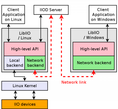
iiod是IIO守护进程,IIO测试程序包括:iio_info、iio_genxml、iio_attr、iio_adi_xflow_check、iio_readdev、iio_reg、iio_writedev、iio_stresstest。

libiio提供多种backend:Local backend通过sysfs和内核直接交互;Network backend提供网络访问能力。
iiod作为守护进程提供IIO Network backend交互中转。其他设备可以通过网络将请求发给iiod,得到响应。
Linux本机进程借助libiio直接访问内核设备。
关于libiio更多参考《What is libiio? [Analog Devices Wiki]》、《About libiio [Analog Devices Wiki]》、《IIO Oscilloscope [Analog Devices Wiki]》(一款IIO数据可视化工具)。
参考文档:《手把手教你在Linux下对IIO设备编程访问(附代码)》--QT访问IIO设备代码;《Linux Industrial I/O Subsystem [Analog Devices Wiki]》--ADI总结的关于libiio、IIO Oscilloscope等文档。


【推荐】国内首个AI IDE,深度理解中文开发场景,立即下载体验Trae
【推荐】编程新体验,更懂你的AI,立即体验豆包MarsCode编程助手
【推荐】抖音旗下AI助手豆包,你的智能百科全书,全免费不限次数
【推荐】轻量又高性能的 SSH 工具 IShell:AI 加持,快人一步
· 震惊!C++程序真的从main开始吗?99%的程序员都答错了
· 【硬核科普】Trae如何「偷看」你的代码?零基础破解AI编程运行原理
· 单元测试从入门到精通
· 上周热点回顾(3.3-3.9)
· winform 绘制太阳,地球,月球 运作规律
2017-02-07 WireShark抓包工具使用