OpenHarmony开发12 —— 在BearPi上实现UART数据读写并且移植到Hispark上
OpenHarmony开发12 —— 在BearPi上实现UART数据读写并且移植到Hispark上
好久没有工作了!前段时间因为做别的开发,还有过年,休息了一周,希望东西都没忘
在BearPi上实现UART数据读写
-
老规矩,连接虚拟机,我们需要做的是UART串口通信
-
阅读UART接口:
- UartInit()
- UartWrite()
- UartRead()
-
硬件部分看不懂,软件设计发现需要修改波特率,先保留代码,不知道在两块板子的波特率和数据位之间有什么不一样的要求
-
按照教程,修改
Build.gn
# Copyright (c) 2020 Nanjing Xiaoxiongpai Intelligent Technology Co., Ltd.
# Licensed under the Apache License, Version 2.0 (the "License");
# you may not use this file except in compliance with the License.
# You may obtain a copy of the License at
#
#     http://www.apache.org/licenses/LICENSE-2.0
#
# Unless required by applicable law or agreed to in writing, software
# distributed under the License is distributed on an "AS IS" BASIS,
# WITHOUT WARRANTIES OR CONDITIONS OF ANY KIND, either express or implied.
# See the License for the specific language governing permissions and
# limitations under the License.

import("//build/lite/config/component/lite_component.gni")

lite_component("app") {
    features = [
        #"A1_kernal_thread:thread_example",
        #"A2_kernel_timer:timer_example",
        #"A3_kernel_event:event_example",
        #"A4_kernel_mutex:mutex_example",
        #"A5_kernel_semaphore:semaphore_example",
        #"A6_kernel_message:message_example",

        #"B1_basic_led_blink:led_example",
        #"B2_basic_button:button_example",
        #"B3_basic_pwm_led:pwm_example",
        #"B4_basic_adc:adc_example",
        #"B5_basic_i2c_nfc:i2c_example",
        "B6_basic_uart:uart_example",

        #"C1_e53_sf1_mq2:e53_sf1_example",
        #"C2_e53_ia1_temp_humi_pls:e53_ia1_example",
        #"C3_e53_sc1_pls:e53_sc1_example",
        #"C4_e53_sc2_axis:e53_sc2_example",
        #"C5_e53_is1_infrared:e53_is1_example",

        #"D1_iot_wifi_ap:wifi_ap",
        #"D2_iot_wifi_sta_connect:wifi_sta_connect",
        #"D3_iot_udp_client:udp_client",
        #"D4_iot_tcp_server:tcp_server",
        #"D5_iot_mqtt:iot_mqtt",
        #"D6_iot_cloud_oc:oc_mqtt",
        #"D7_iot_cloud_onenet:onenet_mqtt",
        #"D8_iot_cloud_oc_smoke:cloud_oc_smoke",
        #"D9_iot_cloud_oc_light:cloud_oc_light",
        #"D10_iot_cloud_oc_manhole_cover:cloud_oc_manhole_cover",
        #"D11_iot_cloud_oc_infrared:cloud_oc_infrared",
        #"D12_iot_cloud_oc_agriculture:cloud_oc_agriculture",
        #"D13_iot_cloud_oc_gps:cloud_oc_gps",
    ]
}
- 打开putty进行编译,输入
hpm dist
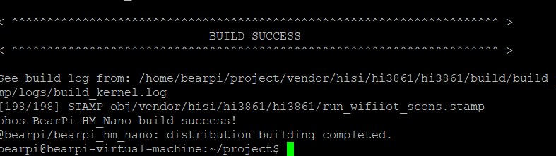
-
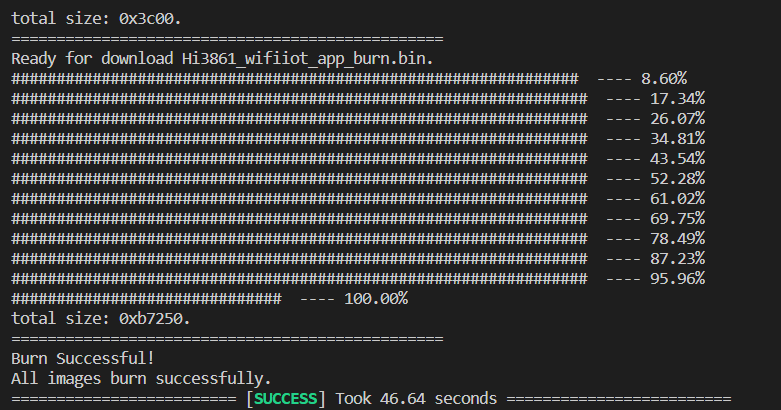
复制出
Hi3861_wifiiot_app_allinone.bin,连接之后进行烧录记得选择auto burn 还有把波特率选择921600
-
监听接口之后尝试运行
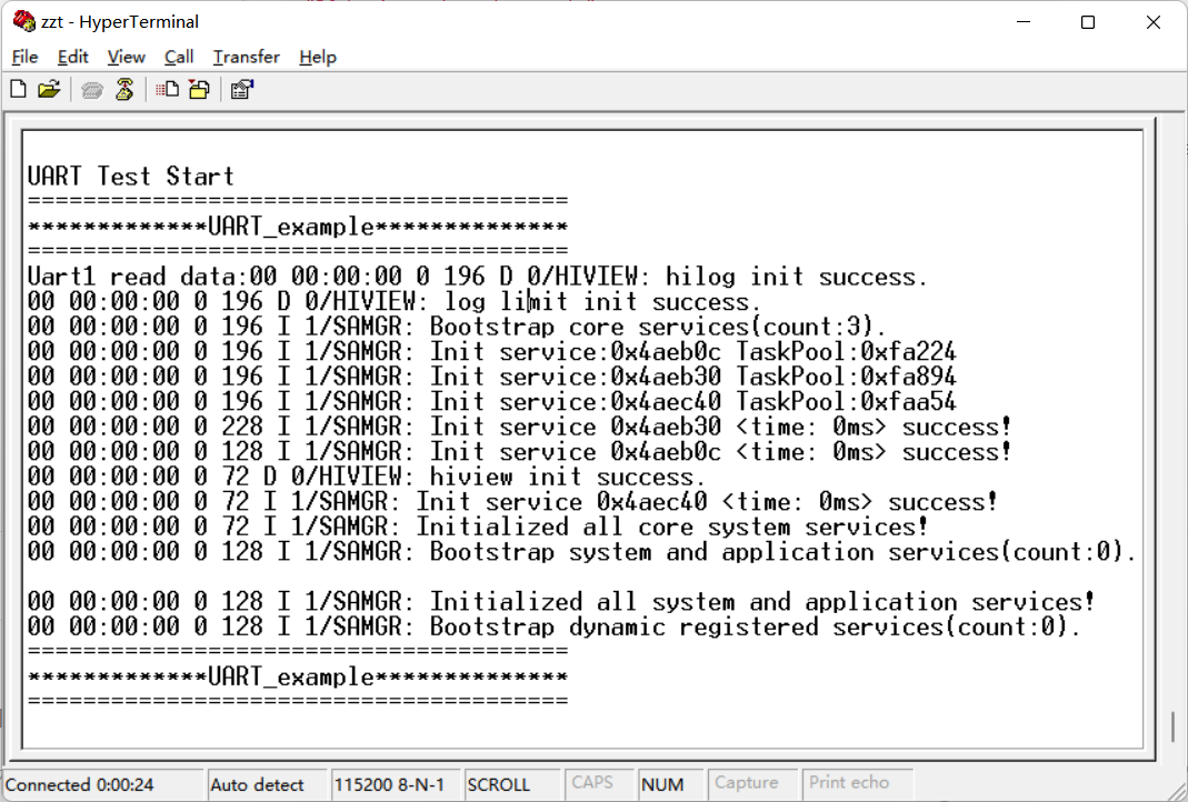
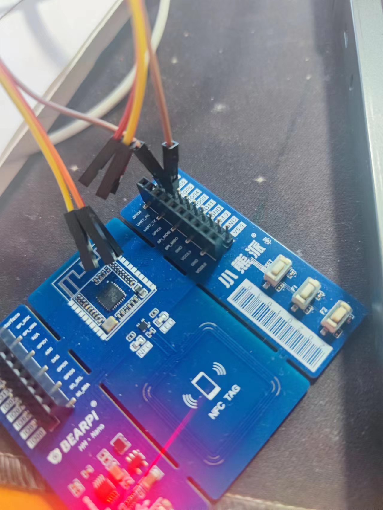
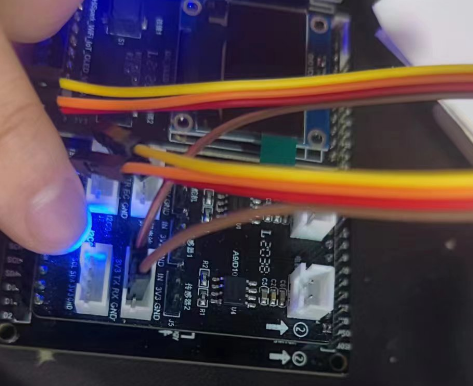
- 把开发板上的E53接口的TX与RX用杜邦线连接
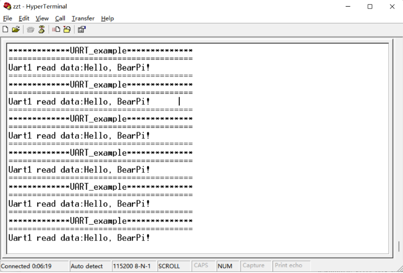
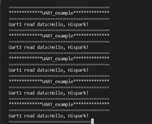
- 实验结果
代码移植
-
观察到build.gn中依然有
cmsis/2.0,所以换成我们之前找到的最新路径"//third_party/cmsis/CMSIS/RTOS2/Include", -
删除掉头文件引入的
errno.h -
build一次,发现报错
不用说,肯定是因为
"//base/iot_hardware/interfaces/kits/wifiiot_lite",这个地址出问题了! -
于是我们尝试寻找,最终发现并修改为
"//base/iot_hardware/peripheral/interfaces/kits", -
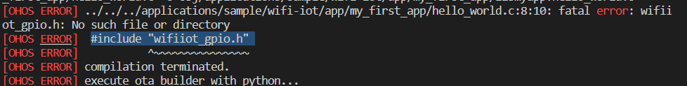
再次编译,发现并没有这些"wifiiot_gpio.h"的文件,于是尝试寻找,最终原来是源码在1.0版本到1.1版本整合的时候进行了归类整理,具体代码改动很多。这里直接放我修改之后可以通过编译的代码了
#include <stdio.h>
#include <string.h>
#include <unistd.h>

#include "ohos_init.h"
#include "cmsis_os2.h"

//#include "wifiiot_errno.h"
//#include "wifiiot_gpio.h"
//#include "wifiiot_gpio_ex.h"
//#include "wifiiot_adc.h"
//#include "wifiiot_uart.h"
#include "iot_errno.h"
#include "iot_gpio.h"
#include "iot_uart.h"

#define UART_TASK_STACK_SIZE 1024 * 8
#define UART_TASK_PRIO 25
#define UART_BUFF_SIZE 1000
#define WIFI_IOT_UART_IDX_1 1

static const char *data = "Hello, Hispark!\r\n";

static void UART_Task(void)
{
    uint8_t uart_buff[UART_BUFF_SIZE] = {0};
    uint8_t *uart_buff_ptr = uart_buff;
    uint32_t ret;

    //WifiIotUartAttribute uart_attr = {
	IotUartAttribute uart_attr = {

        //baud_rate: 9600
        .baudRate = 9600,

        //data_bits: 8bits
        .dataBits = 8,
        .stopBits = 1,
        .parity = 0,
    };

    //Initialize uart driver
	//ret = IoTUartInit(WIFI_IOT_UART_IDX_1, &uart_attr, NULL);
	ret = IoTUartInit(WIFI_IOT_UART_IDX_1, &uart_attr);
    if (ret != IOT_SUCCESS)
    {
        printf("Failed to init uart! Err code = %d\n", ret);
        return;
    }
    printf("UART Test Start\n");
    while (1)
    {
        printf("=======================================\r\n");
        printf("*************UART_example**************\r\n");
        printf("=======================================\r\n");

        //通过串口1发送数据
        IoTUartWrite(WIFI_IOT_UART_IDX_1, (unsigned char *)data, strlen(data));

        //通过串口1接收数据
        IoTUartRead(WIFI_IOT_UART_IDX_1, uart_buff_ptr, UART_BUFF_SIZE);

        printf("Uart1 read data:%s", uart_buff_ptr);
        usleep(1000000);
    }
}
void HelloWorld(void)
{
    osThreadAttr_t attr;

    attr.name = "UART_Task";
    attr.attr_bits = 0U;
    attr.cb_mem = NULL;
    attr.cb_size = 0U;
    attr.stack_mem = NULL;
    attr.stack_size = UART_TASK_STACK_SIZE;
    attr.priority = UART_TASK_PRIO;

    if (osThreadNew((osThreadFunc_t)UART_Task, NULL, &attr) == NULL)
    {
        printf("[ADCExample] Falied to create UART_Task!\n");
    }
}
//SYS_RUN(HelloWorld);
APP_FEATURE_INIT(HelloWorld);
- Build.gn
static_library("myapp") {
    sources = [
        "hello_world.c",
    ]


    include_dirs = [
        "//utils/native/lite/include",
        "//base/iot_hardware/peripheral/interfaces/kits",
        "//third_party/cmsis/CMSIS/RTOS2/Include",
    ]

}
- 成功烧录
- 运行尝试
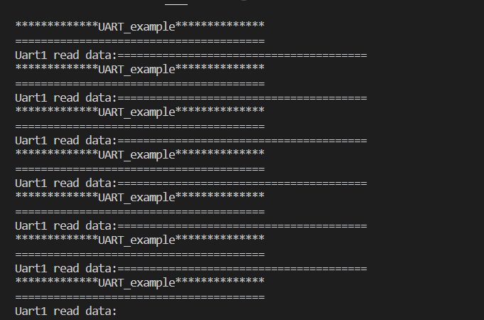
- 连接杜邦线之后,试验成功

 浙公网安备 33010602011771号