

【WCH蓝牙系列芯片】-基于CH582开发板按键控制LED灯
-------------------------------------------------------------------------------------------------------------------------------------
本文主要介绍CH582的GPIO的基础外设的使用,并且利用GPIO外设点亮LED灯和按键扫描功能。将两者结合,实现按键控制LED灯的状态。
<控制LED灯-硬件电路设计>
从沁恒官网中可以下载CH582开发板的原理图PDF版本,下载网址:https://www.wch.cn/downloads/CH583EVT_ZIP.html,
在下载的CH583EVT文件中,打开PUB>CH583SCH,在原理图中可以找到开发板上已焊接两个LED灯分别对应LED1和LED2,如图所示。
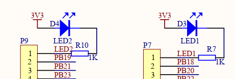
从图中可以看出,LED灯串接一个IK限流电阻,LED正极接电源3.3V,另一端接网络端口标识LED1、LED2。只需要当LED1和LED2引脚端口输出一个低电平,可以导通LED灯,使其点亮。在此实验中,采用自己焊接的LED硬件电路,如图所示。

<控制LED灯-软件程序设计>
在程序设计中,先配置系统时钟源和时钟频率,先对PA0、PA4、PA6三个引脚置为高电平,再初始化LED对应连接IO端口(PA0、PA4、PA6),设置引脚为推挽输出最大5mA模式。这样可以防止刚上电时,引脚端口未置高电平,IO口状态不确定,LED会被点亮,出现BUG。
在程序中通过设置IO端口的高低电平控制LED状态,也可实现LED流水灯的效果。LED.C函数如下。

  1 #include "CH58x_common.h"
  2
  3
  4 void LED_Init(void)
  5 {
  6    SetSysClock(CLK_SOURCE_PLL_60MHz);  //配置系统时钟源和时钟频率
  7
  8    //初始化GPIO口
  9    GPIOA_SetBits(GPIO_Pin_4);
 10    GPIOA_SetBits(GPIO_Pin_6);
 11    GPIOA_SetBits(GPIO_Pin_0);
 12    GPIOA_ModeCfg(GPIO_Pin_4, GPIO_ModeOut_PP_5mA);  ////推挽输出最大5mA
 13    GPIOA_ModeCfg(GPIO_Pin_6, GPIO_ModeOut_PP_5mA);
 14    GPIOA_ModeCfg(GPIO_Pin_0, GPIO_ModeOut_PP_5mA);
 15 }
 16 //LED亮
 17 void LED1_ON(void)
 18 {
 19     GPIOA_ResetBits(GPIO_Pin_4); //PA4置低电平
 20
 21 }
 22 //LED灭
 23 void LED1_OFF(void)
 24 {
 25     GPIOA_SetBits(GPIO_Pin_4); //PA4置高电平
 26 }
 27
 28 //LED1翻转
 29 void LED1_Turn(void)
 30 {
 31     if (GPIOA_ReadPortPin(GPIO_Pin_4) == 0)  //读取PA4端口是否为低电平
 32     {
 33         GPIOA_SetBits(GPIO_Pin_4); //PA4置高电平
 34     }
 35     else
 36     {
 37         GPIOA_ResetBits(GPIO_Pin_4); //PA4置低电平
 38     }
 39
 40 }
 41
 42
 43 void LED2_ON(void)
 44 {
 45     GPIOA_ResetBits(GPIO_Pin_6); //PA6置低电平
 46 }
 47
 48 void LED3_ON(void)
 49 {
 50     GPIOA_ResetBits(GPIO_Pin_0); //PA0置低电平
 51 }
 52
 53
 54
 55
 56 void LED2_OFF(void)
 57 {
 58     GPIOA_SetBits(GPIO_Pin_6); //PA6置高电平
 59 }
 60
 61 void LED3_OFF(void)
 62 {
 63     GPIOA_SetBits(GPIO_Pin_0); //PA0置高电平
 64 }
 65
 66
 67
 68 //LED2翻转
 69 void LED2_Turn(void)
 70 {
 71     if (GPIOA_ReadPortPin(GPIO_Pin_6) == 0)
 72     {
 73         GPIOA_SetBits(GPIO_Pin_6); //PA6置高电平
 74     }
 75     else
 76     {
 77         GPIOA_ResetBits(GPIO_Pin_6); //PA6置低电平
 78     }
 79
 80 }
 81
 82 //LED3翻转
 83 void LED3_Turn(void)
 84 {
 85     if (GPIOA_ReadPortPin(GPIO_Pin_0) == 0)
 86     {
 87         GPIOA_SetBits(GPIO_Pin_0); //PA0置高电平
 88     }
 89     else
 90     {
 91         GPIOA_ResetBits(GPIO_Pin_0); //PA0置低电平
 92     }
 93
 94 }
 95
 96 //LED流水灯
 97 void LED_RUN(void)
 98 {
 99  GPIOA_ResetBits(GPIO_Pin_4);
100  GPIOA_SetBits(GPIO_Pin_6);
101  GPIOA_SetBits(GPIO_Pin_0);
102  DelayMs(500);
103
104  GPIOA_ResetBits(GPIO_Pin_6);
105  GPIOA_SetBits(GPIO_Pin_0);
106  GPIOA_SetBits(GPIO_Pin_4);
107  DelayMs(500);
108
109  GPIOA_ResetBits(GPIO_Pin_0);
110  GPIOA_SetBits(GPIO_Pin_6);
111  GPIOA_SetBits(GPIO_Pin_4);
112  DelayMs(500);
113 }
114
115 void LED_shan(void)
116 {
117     GPIOA_ResetBits(GPIO_Pin_4);
118     GPIOA_ResetBits(GPIO_Pin_6);
119     GPIOA_ResetBits(GPIO_Pin_0);
120     DelayMs(500);
121
122     GPIOA_SetBits(GPIO_Pin_0);
123     GPIOA_SetBits(GPIO_Pin_6);
124     GPIOA_SetBits(GPIO_Pin_4);
125     DelayMs(500);
126 }
<按键扫描-硬件电路设计>
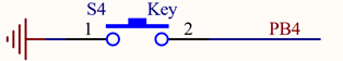
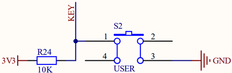
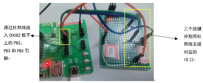
在所提供的原理图中,可知CH582开发板上已焊接一个按键,通过对PB4引脚的控制可对按键扫描进行读取。在本实验中,采用自己所焊接的按键扫描硬件电路。硬件如图所示,当未按下按键S2时,此时KEY端口为高电平,一旦按下按键,此时KEY端口有高电平转变为低电平。采用这样的硬件电路,设计三个按键;在程序设计过程中,只需要检测不同的KEY是否有低电平,从而判断哪个按键是否被按下。
<按键扫描-软件程序设计>
在按键扫描过程中,当按键按下时会出现按键抖动的现象,这是因为按键内部采用机械弹簧片进行通断,在按下和松开的一瞬间会出现一连串的抖动。如图所示。
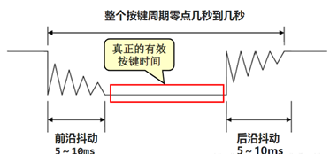
为此解决这个问题,可以有硬件消抖和软件消抖两种方式。在本实验中,采用延时函数的软件消抖。
- 在检测按键闭合后,延时20ms时间,以此去除前沿抖动;
- 再检测按键状态,判断按键是否处于闭合状态,才能执行按键对应的操作;
- 在松开按键后,采用延时函数方式以此去除后沿抖动。


 1 #include "CH58x_common.h"
 2
 3
 4
 5 void Key_Init(void)
 6 {
 7     SetSysClock(CLK_SOURCE_PLL_60MHz);  //配置系统时钟源和时钟频率
 8
 9     //初始化GPIO口
10     GPIOB_ModeCfg(GPIO_Pin_2, GPIO_ModeIN_PU);  ////上拉输入
11     GPIOB_ModeCfg(GPIO_Pin_3, GPIO_ModeIN_PU);
12     GPIOB_ModeCfg(GPIO_Pin_5, GPIO_ModeIN_PU);
13
14 }
15
16 //读取KEY的值
17 uint8_t Key_GetNum(void)
18 {
19     uint8_t KeyNum = 0;
20     //按键1
21     if (GPIOB_ReadPortPin(GPIO_Pin_2) == 0)   //读取PB2的电平状态
22     {
23         DelayMs(20);//软件按键消抖
24         while (GPIOB_ReadPortPin(GPIO_Pin_2) == 0);
25         DelayMs(20);
26         KeyNum = 1;
27     }
28
29     //按键2
30     if (GPIOB_ReadPortPin(GPIO_Pin_3) == 0)  //读取PB3的电平状态
31     {
32         DelayMs(20);//软件按键消抖
33         while (GPIOB_ReadPortPin(GPIO_Pin_3) == 0);
34         DelayMs(20);
35         KeyNum = 2;
36     }
37
38     //按键3
39     if (GPIOB_ReadPortPin(GPIO_Pin_5) == 0)    //读取PB3的电平状态
40     {
41         DelayMs(20);//软件按键消抖
42         while (GPIOB_ReadPortPin(GPIO_Pin_5) == 0);
43         DelayMs(20);
44         KeyNum = 3;
45     }
46
47
48     return KeyNum;
49
50
51 }
程序中,将PB2、PB3、PB5都初始化为上拉输入模式,通过读取IO口的电平状态,配合软件延时消抖,从而识别按键扫描状态,判断具体哪个按键被按下。
 1 #include "CH58x_common.h"
 2 #include "LED.h"
 3 #include "KEY.h"
 4
 5 uint8_t KEY_num;
 6
 7 int main()
 8 {
 9     LED_Init();  //初始化LED
10     Key_Init();  //按键初始化
11
12
13     while(1)
14     {
15         KEY_num = Key_GetNum();
16         if (KEY_num == 1)
17         {
18             LED1_Turn();  //LED1翻转
19             DelayMs(500);
20             LED2_Turn();  //LED2翻转
21             DelayMs(500);
22             LED3_Turn();  //LED3翻转
23             DelayMs(500);
24         }
25         if (KEY_num == 2)
26         {
27             LED_RUN();     //流水灯
28             DelayMs(1000);
29         }
30         if (KEY_num == 3)
31         {
32             LED_shan();  //LED闪烁
33         }
34     }
35 }
先添加"LED.h"和"KEY.h"头文件,在主函数中,初始化LED和按键,通过判断哪个按键按下,执行对应的LED灯闪烁效果。从而实现按键控制LED的现象。


【推荐】国内首个AI IDE,深度理解中文开发场景,立即下载体验Trae
【推荐】编程新体验,更懂你的AI,立即体验豆包MarsCode编程助手
【推荐】抖音旗下AI助手豆包,你的智能百科全书,全免费不限次数
【推荐】轻量又高性能的 SSH 工具 IShell:AI 加持,快人一步
· 10年+ .NET Coder 心语 ── 封装的思维:从隐藏、稳定开始理解其本质意义
· 地球OL攻略 —— 某应届生求职总结
· 周边上新:园子的第一款马克杯温暖上架
· 提示词工程——AI应用必不可少的技术
· Open-Sora 2.0 重磅开源!