
《操作系统真相还原》实验记录2.3——实现中断机制
 本文章通过构造简易中断处理函数(汇编实现)、初始化IDT、初始化中断控制代理8259A,实现时钟中断控制。
零、程序编写初步分析
- 中断处理程序编写初步计划如下【图中关系为:调用者 -> 被调用函数】

- init_all 函数用来初始化所有的设备及数据结构,我们打算在kernel内核的main主函数中调用它来完成初始化工作。
- init_all 首先调用 idt_init,它用来初始化中断相关的内容。
- 由于初始化也要分成几部分来做,这由 pic_init 和 idt_desc_init 分别完成。
- pic_init 用来初始化可编程中断控制器8259A。
- PIC 是“可编程中断控制器Programmable Interrupt Controller”的简称,而 8259A 也是 PIC 的一种。
- 在用 pic_init 函数初始化 8259A 后,我们还需要初始化中断描述符表IDT,这是用 idt_desc_init 来完成的。
- 在这个初始化过程中,最核心、最底层的便是 ide_desc_init,在该函数中我们要填充中断处理程序的地址到 IDT 中,所以我们在执行该函数之前,需要提前把所有中断处理函数准备好。
- 在 idt_init 完成之后便可以加载 IDT ,到此打开中断的条件便准备好了。
一、前置知识点
1.1 宏
- 宏,即Macro。宏是用来代替重复性输入的,是一段代码的模板。不同的编译器基本上都会提供这样的预处理指令。
- 宏属于预处理指令。预处理指令是编译器为用户编码方便而提供的、仅被编译器中的预处理器支持的符号,并不是处理器直接支持的指令,故属于伪指令。
- 预处理指令是指在编译前,编译器需要预先处理的指令,也就是在编译前先扫描一下代码,将一些编译器提供的伪指令展开替换成具体的语言符号后编译器才能识别,也就是说代码在预处理之后,其中的预处理指令(伪指令)全都会不见的。而完成预处理工作的软件通常称为预处理器,其实就是一个功能模块,伪指令的意义只能由编译器中的预处理器知道。
- 在汇编中定义宏有多种方式。
- 如果是定义单行的宏,可以用
#define指令来实现,这和C语言中的define用法一致。 - 如果是定义多行的宏,就要用
%macro来实现。

- 如果是定义单行的宏,可以用
二、第一版中断处理流程:完成最简单的中断处理——时钟中断
- 我们将通过操作 8259A 打开中断,完成第一个中断处理,即时钟中断处理。
2.1 用汇编语言实现中断处理程序
2.1.1 代码说明
- 文件名:kernel.S
- 用途
- Interrupt processing program
- 创建33个中断处理程序的入口地址数组intr_entry_table。
2.1.2 相关资料
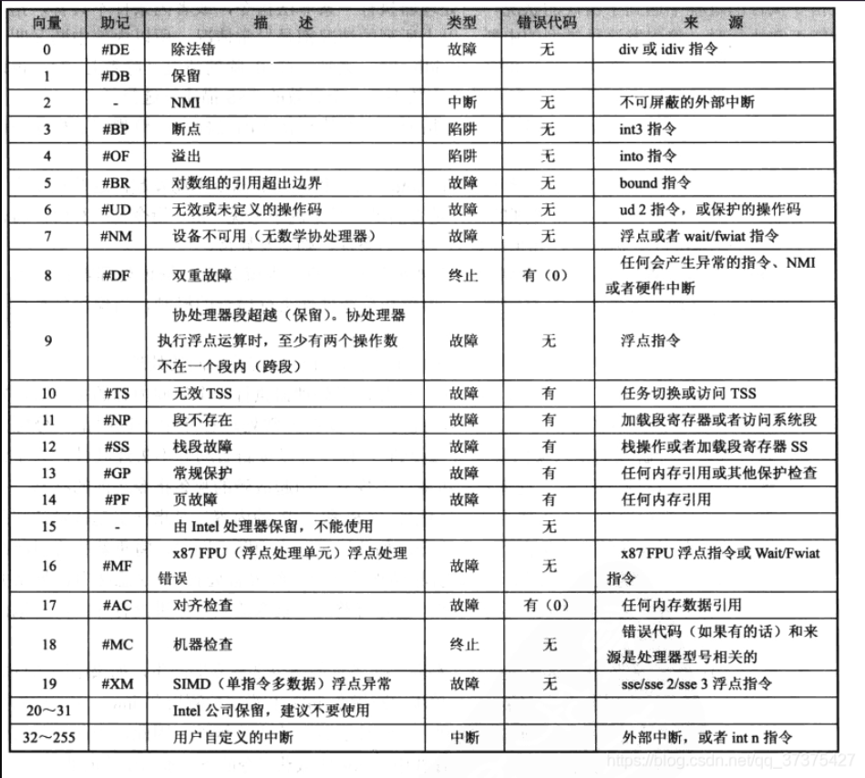
- 异常与中断表
2.1.2 代码
kernel.S
[bits 32]
%define ERROR_CODE nop  ;nop: no operate.
%define ZERO push 0

extern put_str

section .data
intr_str db "interrupt occur!", 0xa, 0
global intr_entry_table
intr_entry_table:         ;this address will be used to store all entrances of interrupt program(it will be a array because of "section .data").

%macro VECTOR 2      ;macro of row and parameter's number is 2.
section .text
intr%1entry:        ;intr + %1 + entry to create this name.
   %2          ;if %2=ZERO,push 0, if %2=ERROR_CODE,nop.
   push intr_str
   call put_str
   add esp, 4     ;skip the intr_str in stack.

   mov al, 0x20   ;the commend of "EOI(end of interrupt)"
   out 0xa0, al   ;write to 8259A
   out 0x20, al

   add esp, 4     ;skip the error_code or 0 in stack
   iret

section .data     ;after compile,these port of ".data" will be merged, so the commend of "dd" will write address of "intr%1entry" below "intr_entry_table:" and these address compose a array.
   dd intr%1entry

%endmacro

VECTOR 0x00,ZERO
VECTOR 0x01,ZERO
VECTOR 0x02,ZERO
VECTOR 0x03,ZERO
VECTOR 0x04,ZERO
VECTOR 0x05,ZERO
VECTOR 0x06,ZERO
VECTOR 0x07,ZERO
VECTOR 0x08,ERROR_CODE
VECTOR 0x09,ZERO
VECTOR 0x0a,ERROR_CODE
VECTOR 0x0b,ERROR_CODE
VECTOR 0x0c,ERROR_CODE
VECTOR 0x0d,ERROR_CODE
VECTOR 0x0e,ERROR_CODE
VECTOR 0x0f,ZERO
VECTOR 0x10,ZERO
VECTOR 0x11,ERROR_CODE
VECTOR 0x12,ZERO
VECTOR 0x13,ZERO
VECTOR 0x14,ZERO
VECTOR 0x15,ZERO
VECTOR 0x16,ZERO
VECTOR 0x17,ZERO
VECTOR 0x18,ZERO
VECTOR 0x19,ZERO
VECTOR 0x1a,ZERO
VECTOR 0x1b,ZERO
VECTOR 0x1c,ZERO
VECTOR 0x1d,ZERO
VECTOR 0x1e,ERROR_CODE
VECTOR 0x1f,ZERO

VECTOR 0x20,ZERO   ;this vector of interrupt can be defined by user and above all are used by CPU dafault.
2.2 创建中断描述符表IDT,安装中断处理程序
2.2.1 代码说明
- 文件名:interrupt.c
- 用途:将上文中的中断处理程序地址装载到中断描述符中。
- 注意,此时的所有中断处理程序地址数据均以数组元素的形式存储在以“intr_entry_table: ”为起始地址的内存中。
- 用途:将上文中的中断处理程序地址装载到中断描述符中。
- 文件名:global.h
- 用途:头文件
2.2.2 相关资料
- 函数编写逻辑【注意调用关系】
- 中断门描述符结构体依据

- 静态函数声明:在函数的返回类型前面加上关键字static,函数就被定义成为静态函数
- 静态函数会被自动分配在一个一直使用的存储区,直到程序结束才从内存消失,避免调用函数时压栈出栈,速度快很多。
- 其他文件可以定义相同名字的函数,不会发生冲突。
- 静态函数不能被其它文件调用,作用于仅限于本文件。
- C结构体
- 参考资料:菜鸟教程
2.2.3 代码
interrupt.h
#ifndef __KERNEL_INTERRUPT_H
#define __KERNEL_INTERRUPT_H
#include "stdint.h"
typedef void* intr_handler;  //declare a type of point.
#endif
global.h
#ifndef __KERNEL_GLOBAL_H
#define __KERNEL_GLOBAL_H
#include "stdint.h"

#define RPL0 0 //Request Privilege Level of 0,will be used to pad descriptor.
#define RPL1 1
#define RPL2 2
#define RPL3 3

#define TI_GDT 0
#define TI_LDT 1

#define SELECTOR_K_CODE  ((1 << 3) + (TI_GDT << 2) + RPL0) //selector kernel code.
#define SELECTOR_K_DATA  ((2 << 3) + (TI_GDT << 2) + RPL0)
#define SELECTOR_K_STACK SELECTOR_K_DATA
#define SELECTOR_K_GS    ((3 << 3) + (TI_GDT << 2) + RPL0)

/*The attrirbute of IDT's descriptor*/
#define IDT_DESC_P     1
#define IDT_DESC_DPL0  0
#define IDT_DESC_DPL3  3
#define IDT_DESC_32_TYPE   0xE
#define IDT_DESC_16_TYPE   0x6

#define IDT_DESC_ATTR_DPL0  ((IDT_DESC_P << 7) + (IDT_DESC_DPL0 << 5) + IDT_DESC_32_TYPE)
#define IDT_DESC_ATTR_DPL3  ((IDT_DESC_P << 7) + (IDT_DESC_DPL3 << 5) + IDT_DESC_32_TYPE)

#endif
interrupt.c
#include "interrupt.h"
#include "stdint.h"
#include "global.h"

#define IDT_DESC_CNT 0x21  //the quantity of interrupt which we support at this time.

struct gate_desc {  //the struct of interrupt gate descriptor.
   uint16_t  func_offset_low_word;
   uint16_t  selector;
   uint8_t   dcount;  //fixed value,don't think about it.
   uint8_t   attribute;
   uint16_t  func_offset_high_word;
};

//static function declaration
static void make_idt_desc(struct gate_desc* p_gdesc, uint8_t attr, intr_handler function);
static struct gate_desc idt[IDT_DESC_CNT]; //it is an array of interrupt descriptor(IDT).

extern intr_handler intr_entry_table[IDT_DESC_CNT];  //it's also an array of "address of each interrupt handler",and the type of "intr_handle" is defined in document which is named "interrupt.h".

/*Create interrupt gate descriptor*/
static void make_idt_desc(struct gate_desc* p_gdesc, uint8_t attr, intr_handler function) {
   p_gdesc->func_offset_low_word = (uint32_t)function & 0x0000FFFF; //function: address of each interrupt handler.
   p_gdesc->selector = SELECTOR_K_CODE; //it is defined in document which is named "global.h" and it indicates a selector which is point to code segement in kernel.
   p_gdesc->dcount = 0;
   p_gdesc->attribute = attr;
   p_gdesc->func_offset_high_word = ((uint32_t)function & 0xFFFF0000) >> 16;
}

/*Initialize IDT*/
static void idt_desc_init(void) {
   for(int i = 0; i < IDT_DESC_CNT; i++) {
      make_idt_desc(&idt[i], IDT_DESC_ATTR_DPL0, intr_entry_table[i]);  //key program
   }
   put_str("idt_desc_init done\n");
}

/*Finish all initial work about interrupt*/
void idt_init() {
   put_str("idt_init start\n");
   idt_desc_init();  //initialize the idt descriptor
   pic_init();  //it will be done right away.(the function will be used to initialize )

   /*load IDT*/
   uint64_t idt_operand = ((sizeof(idt) - 1) | ((uint64_t)(uint32_t)idt << 16)); //iperand: the object which an operation is to be done.
   asm volatile("lidt %0": : "m"(idt_operand));
   put_str("idt_init done\n");
}
2.3 用内联汇编实现端口 I/O 函数
2.3.1 代码说明
- 和中断相关的数据准备好后,接下来需要把中断代理8259A设置好。
- 对 8259A 或任何硬件的控制都要通过端口,因此在进行下一步之前,需要将常用的端口读写功能封装成C函数,这就用到了内联汇编。
- 我们将有关端口操作的函数定义在 io.h 文件中。
2.3.2 相关资料
- inline 关键字
- inline关键字建议编译器将函数编译为内嵌的方式。所谓内嵌函数,就是将所调用的函数体的内容,在该函数的调用处,原封不动地展开,这样编译后的代码中将不包含 call 指令,因此不属于函数调用,而是顺次执行。虽然这会让程序大一些,但减少了函数调用及返回时的现场保护及恢复工作,提升了端口读写效率。
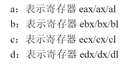
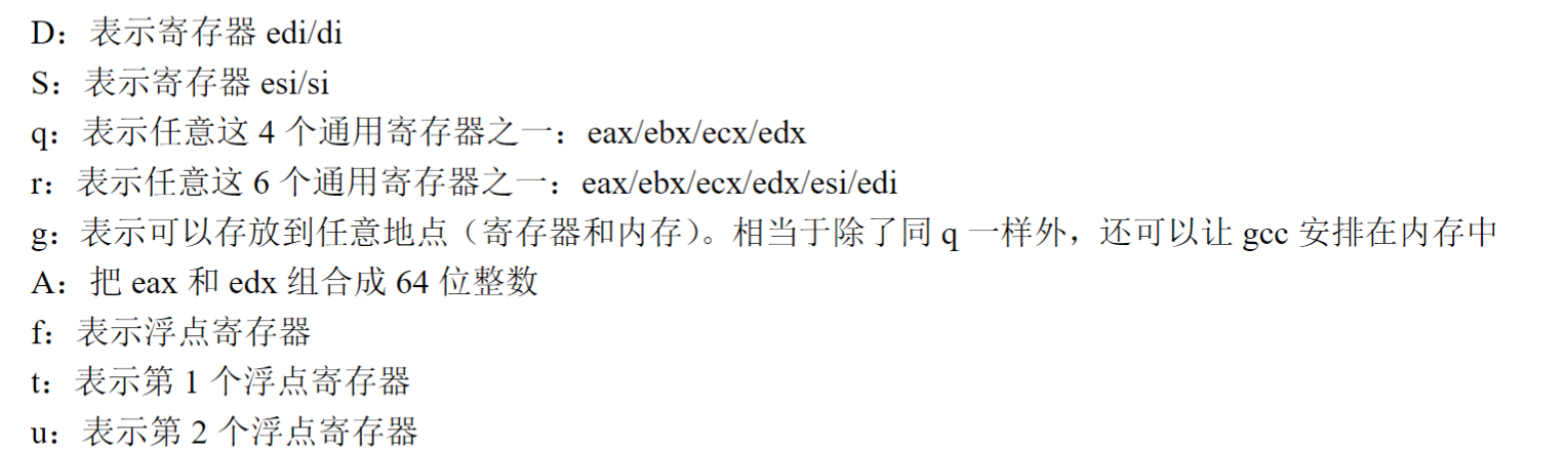
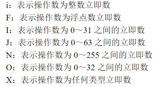
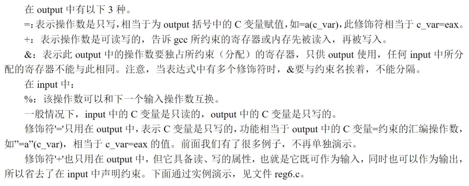
- AT&T汇编语法中的“约束”及操作数类型修饰符
- 内存约束
- m:表示操作数可以使用任意一种内存形式。
- m:表示操作数可以使用任意一种内存形式。
- 内存约束
2.3.3 代码
io.h
#ifndef __LIB_IO_H
#define __LIB_IO_H
#include "stdint.h"

/*
First function: outb()
function:
   write one byte to port.
parameters:
   uint16_t: the type of unsigned int and it's 16bit value.
*/
static inline void outb(uint16_t port, uint8_t data) {
   asm volatile ("outb %b0, %w1" : : "a"(data), "Nd"(port)); //The parameter of "N" indicate that the port number is between 0 and 255.
}

/*
Second function: outsw()
function:
   write more byte to port(the unit is 2byte.)
parameters:
   void* addr: it means the parameter's type of addr is point.
   S: esi/si
directives:
   rep: repeat,and "cx" register self-subtraction unless it's value is 0.
   outsw(assembly language): write 16bit data from address which is pointed by ds:esi to port.
   cld: clean direction, this directive can set the flag of DF to 0, then, register's value of "si" will be increased by length of data.
*/
static inline void outsw(uint16_t port, const void* addr, uint32_t word_cnt) {
   asm volatile ("cld; rep outsw" : "+S"(addr), "+c"(word_cnt) : "d"(port));
}

/*
Third fuction: inb()
function:
   read one byte from port.
*/
static inline uint8_t inb(uint16_t port) {
   uint8_t data;
   asm volatile ("inb %w1, %b0" : "=a"(data) : "Nd"(port));
   return data;
}

/*
Forth fuction: insw()
function:
   read more byte from port.
parameters:
   D: edi/di
   "memory": we notice gcc that we changed memory.
directives:
   insw(assembly language): read 16bit data from port to address which is pointed by es:edi.
*/""
static inline void insw(uint16_t port, void* addr, uint32_t word_cnt) {
   asm volatile ("cld; rep insw" : "+D"(addr), "+c"(word_cnnt) : "d"(port) : "memory");
}

#endif
2.4 设置8259A
2.4.1 代码说明
- 在准备好中断描述符及io操作函数后,接下来我们对 8259A 进行编程。
- 我们拿位于主片上的 IR0 引脚上的时钟中断举例,位于其他引脚的外部中断信号则全部屏蔽。
- 屏蔽某个外部设备中断信号可以通过设置位于 8259A 中的中断屏蔽寄存器 IMR 来实现,只要将相应位置 1 就达到了屏蔽相应中断源信号的目的。
2.4.2 相关资料
- 8259A:可屏蔽中断的代理
- 中断代理负责对所有中断仲裁,决定哪个中断优先被 CPU 受理。
- 中断代理有很多种,我们这里采用的是较流行的中断代理:Intel 8259A 芯片,即可编程中断控制器(PIC)8259A。
- 8259A 用于管理和控制可屏蔽中断,它表现在:屏蔽外设中断、对它们实行优先级判决、向 CPU 提供中断向量号等功能。而它称为可编程的原因,就是可以通过编程的方式来设置以上功能。
- Intel 处理器共支持 256 个中断,但一个 8259A 只可以管理 8 个中断。
- 为了多支持一些中断设备,硬件制造商提供了另一个解决方案,即将多个 8259A 组合,官方术语就是级联。
- 有了级联这种组合后,每一个 8259A 就被称为 1 片。若采用级联方式,即多片 8259A 芯片串连在一起,最多可级联 9 个,n 片 8259A 通过级联可支持 7n+1 个中断源(原因:主片需要使用x个
- 级联时只能有一片8259A为主片 master,其余的均为从片 slave。来自从片的中断只能传递给主片,再由主片向上传递给 CPU,也就是说只有主片才会向 CPU 发送 INT 中断信号。
- 有了级联这种组合后,每一个 8259A 就被称为 1 片。若采用级联方式,即多片 8259A 芯片串连在一起,最多可级联 9 个,n 片 8259A 通过级联可支持 7n+1 个中断源(原因:主片需要使用x个
- 8259A编程
- 8259A 的编程就是对它进行初始化,设置主片与从片的级联方式,指定起始中断向量号以及设置各种工作模式。具体编程方式就是写入 ICW 和 OCW 寄存器组。
- ICW 是初始化控制字,共 4 个,ICW1~ICW4,用于初始化 8259A 的各个功能,用来确定是否需要级联、设置起始中断向量号、设置中断结束模式。
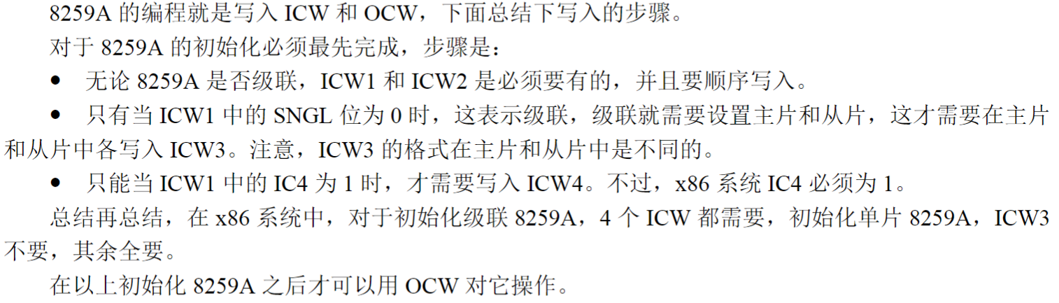
- 8259A 的初始化必须最先完成,之后才可对其进行操作。
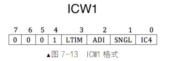
- ICW1 用来初始化 8259A 的连接方式和中断信号的触发方式。连接方式是指用单片工作,还是用多片级联工作,触发方式是指中断请求信号是电平触发,还是边沿触发。
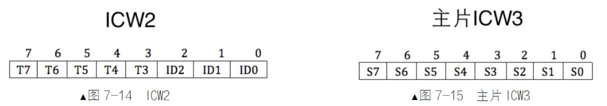
- ICW2 用来设置起始中断向量号。由于每个 8259A 芯片上的 IRQ 接口是顺序排列的,所以这里的设置就是指定 IRQ0 映射到的中断向量号,其他 IRQ 接口对应的中断向量号会顺着自动排下去。
- ICW3 仅在级联的方式下才需要(如果ICW1 中的SNGL 为0),用来设置主片和从片用哪个 IRQ 接口互连。
- ICW4 用于设置 8259A 的工作模式,当 ICW1 中的 IC4 为 1 时才需要ICW4。
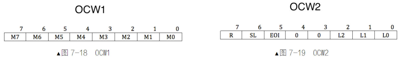
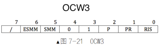
- OCW 是操作控制字,用于和初始化后的 8259A 进行操作命令交互。
- OCW1 用来屏蔽连接在 8259A 上的外部设备的中断信号,实际上就是把 OCW1 写入了 IMR(Interrupt Mask Register) 寄存器。
- 这里的屏蔽是说是否把来自外部设备的中断信号转发给 CPU。由于外部设备的中断都是可屏蔽中断,所以最终还是要受标志寄存器 eflags 中的 IF 位的管束,若 IF 为0,可屏蔽中断全部被屏蔽,也就是说,在 IF 为 0 的情况下,即使8259A 把外部设备的中断向量号发过来,CPU 也置之不理。
- OCW2 用来设置中断结束方式和优先级模式。
- OCW3 用来设定特殊屏蔽方式及查询方式。
- OCW1 用来屏蔽连接在 8259A 上的外部设备的中断信号,实际上就是把 OCW1 写入了 IMR(Interrupt Mask Register) 寄存器。
- ICW 是初始化控制字,共 4 个,ICW1~ICW4,用于初始化 8259A 的各个功能,用来确定是否需要级联、设置起始中断向量号、设置中断结束模式。
- 因为硬盘是接在了8259A从片的引脚上,将来实现文件系统是离不开硬盘的,所以我们这里使用的8259A要采用主、从片级联的方式。在 x86 系统中,对于初始化级联8259A,4 个 ICW 都需要必须严格按照 ICW 1~4 顺序写入。
- ICW1 和 OCW2、OCW3 是用偶地址端口0x20(主片)或0xA0(从片)写入。
- ICW2~ICW4 和 OCW1 是用奇地址端口0x21(主片)或0xA1(从片)写入。

- 8259A 的编程就是对它进行初始化,设置主片与从片的级联方式,指定起始中断向量号以及设置各种工作模式。具体编程方式就是写入 ICW 和 OCW 寄存器组。
2.4.3 代码
intrrupt.c(代码补充)
#include "io.h"

#define PIC_M_CTRL 0X20  //PIC Master Ctrl port.
#define PIC_M_DATA 0x21
#define PIC_S_CTRL 0xa0
#define PIC_S_DATA 0xa1

static void pic_init(void) {
   //initialize master slice.
   outb(PIC_M_CTRL, 0x11);
   outb(PIC_M_DATA, 0x20);

   outb(PIC_M_DATA, 0x04);
   outb(PIC_M_DATA, 0x01);

   //initialize slave slice.
   outb(PIC_S_CTRL, 0x11);
   outb(PIC_S_DATA, 0x28);

   outb(PIC_S_DATA, 0x02);
   outb(PIC_S_DATA, 0x01);

   //only open IR0(the interrupt of click)
   outb(PIC_M_DATA, 0xfe);
   outb(PIC_S_DATA, 0xff);

   put_str("pic_init done\n");
}
2.5 加载IDT,开启中断
2.5.1 代码说明
- 本节是开启中断的最后一个环节:把中断描述符表 IDT 的信息加载到 IDTR 寄存器。
- 由于 C 语言中没有 48 位的数据类型,所以我们用 64 位的变量 idt_operand 来代替,这是没问题的,lidt指令中会取出 48 位数据做操作数,所以咱们只要保证 64 位变量中的前 48 位数据是正确的就行。
2.5.2 相关资料
- IDTR
- 往 IDTR 中加载 IDT 的指令是lidt,lidt的操作数也要符合 IDTR 寄存器的结构,所以 lidt 的操作数也必须是 48 位,低 16 位是界限limit,高 32 位是基址,只不过这 48 位的数据必须位于内存中。
- lidt的语法:
lidt 48位内存数据
- 移位运算符(" << (左移) ", " >> (右移)")
- 左移运算是将一个二进制位的操作数按指定移动的位数向左移动,移出位被丢弃,右边移出的空位一律补0。
2.5.3 代码
interrupt.c(代码补充)
static struct gate_desc idt[IDT_DESC_CNT]; //it is an array of interrupt descriptor(IDT).
   /*load IDT*/
   uint64_t idt_operand = ((sizeof(idt) - 1) | ((uint64_t)(uint32_t)idt << 16)); //iperand: the object which an operation is to be done, (uint32_t) and (uint64_t) is operation to translate value's type.
   asm volatile("lidt %0": : "m"(idt_operand));
   put_str("idt_init done\n");
2.6 编写并运行总初始化函数
2.6.1 代码说明
- init.c
- init_all函数,顾名思义,用来做所有初始化相关的工作,而中断初始化只是其中之一。鉴于这个原因,为将来扩展方便,我们单独写个文件用来调用所有模块的初始化主函数,就像调用 idt_init 一样.
- main.c
- init_all 是由 main.c 中的主函数 main 调用的,因此还需要修改main.c文件。
- init.h
- 头文件,用于声明init_all()函数。
2.6.2 代码
init.h
#ifndef __INIT_H
void init_all(void);
#endif
init.c
#include "init.h"
#include "print.h"
#include "interrupt.h"

void init_all() {
   put_str("init_all\n");
   idt_init();
}
main.c
#include "print.h"
#include "init.h"

void main(void) {
   put_str("I am kernel\n");
   init_all();
   asm volatile("sti");
   /*the directive of "sti" is open interrupt,
   it set eflags's IF to 1,
   so CPU can process the interrupt signal from 8259A.*/
   while(1);
}
三、运行结果

四、第一版中断处理流程组织架构图

五、第二版中断处理流程:改进中断处理程序
interrupt.c
#include "interrupt.h"
#include "stdint.h"
#include "global.h"
#include "io.h"

#define IDT_DESC_CNT 0x21  //the quantity of interrupt which we support at this time.
#define PIC_M_CTRL 0X20
#define PIC_M_DATA 0x21
#define PIC_S_CTRL 0xa0
#define PIC_S_DATA 0xa1


struct gate_desc {  //the struct of interrupt gate descriptor.
   uint16_t  func_offset_low_word;
   uint16_t  selector;
   uint8_t   dcount;  //fixed value,don't think about it.
   uint8_t   attribute;
   uint16_t  func_offset_high_word;
};

//static function declaration
static void make_idt_desc(struct gate_desc* p_gdesc, uint8_t attr, intr_handler function);
static struct gate_desc idt[IDT_DESC_CNT]; //it is an array of interrupt descriptor(IDT).

extern intr_handler intr_entry_table[IDT_DESC_CNT];  //it's also an array of "address of each interrupt handler",and the type of "intr_handle" is defined in document which is named "interrupt.h".

char* intr_name[IDT_DESC_CNT];
intr_handler idt_table[IDT_DESC_CNT];

static void general_intr_handler(uint8_t vec_nr) {
   if(vec_nr == 0x27 || vec_nr == 0x2f) {
      return;
   }
   put_str("int vector : 0x");
   put_int(vec_nr);
   put_char('\n');
}

/*Create interrupt gate descriptor*/
static void make_idt_desc(struct gate_desc* p_gdesc, uint8_t attr, intr_handler function) {
   p_gdesc->func_offset_low_word = (uint32_t)function & 0x0000FFFF; //function: address of each interrupt handler.
   p_gdesc->selector = SELECTOR_K_CODE; //it is defined in document which is named "global.h" and it indicates a selector which is point to code segement in kernel.
   p_gdesc->dcount = 0;
   p_gdesc->attribute = attr;
   p_gdesc->func_offset_high_word = ((uint32_t)function & 0xFFFF0000) >> 16;
}

static void exception_init(void) {
   int i;
   for(i = 0; i < IDT_DESC_CNT; i++) {
      idt_table[i] = general_intr_handler;
      intr_name[i] = "unknow";
   }
   intr_name[0] = "#DE Divide Error";
   intr_name[1] = "#DB Debug Exception";
   intr_name[2] = "NMI Interrupt";
   intr_name[3] = "BP Breakpoint Exception";
   intr_name[4] = "OF Overflow Exception";
   intr_name[5] = "BR BOUND Range Exceeded Exception";
   intr_name[6] = "UD Invalid Opcode Exception";
   intr_name[7] = "NM Device Not Available Exception";
   intr_name[8] = "DF Double Fault Exception";
   intr_name[9] = "Coprocessor Segement Overrun";
   intr_name[10] = "TS Invalid TSS Exception";
   intr_name[11] = "NP Segement Not Present";
   intr_name[12] = "SS Stack Fault Exception";
   intr_name[13] = "GP General Protection Exception";
   intr_name[14] = "PF Page-Faule Exception";
   //intr_name[15] this is holds.
   intr_name[16] = "MF x87 fpu Floating-Point Error";
   intr_name[17] = "AC Alignment Check Exception";
   intr_name[18] = "MC Machine-Check Exception";
   intr_name[19] = "XF SIMD Floation-Point Exception";
}

/*Initialize IDT*/
static void idt_desc_init(void) {
   int i;
   for(i = 0; i < IDT_DESC_CNT; i++) {
      make_idt_desc(&idt[i], IDT_DESC_ATTR_DPL0, intr_entry_table[i]);
   }
   put_str("idt_desc_init done\n");
}

static void pic_init(void) {
   //initialize master slice.
   outb(PIC_M_CTRL, 0x11);
   outb(PIC_M_DATA, 0x20);

   outb(PIC_M_DATA, 0x04);
   outb(PIC_M_DATA, 0x01);

   //initialize slave slice.
   outb(PIC_S_CTRL, 0x11);
   outb(PIC_S_DATA, 0x28);

   outb(PIC_S_DATA, 0x02);
   outb(PIC_S_DATA, 0x01);

   //only open IR0(the interrupt of click)
   outb(PIC_M_DATA, 0xfe);
   outb(PIC_S_DATA, 0xff);

   put_str("pic_init done\n");
}

/*Finish all initial work about interrupt*/
void idt_init() {
   put_str("idt_init start\n");
   exception_init();
   idt_desc_init();
   pic_init();

   /*load IDT*/
   uint64_t idt_operand = ((sizeof(idt) - 1) | ((uint64_t)(uint32_t)idt << 16)); //iperand: the number on which an operation is to be done.
   asm volatile("lidt %0": : "m"(idt_operand));
   put_str("idt_init done\n");
}
kernel.S
[bits 32]
%define ERROR_CODE nop  ;nop: no operate.
%define ZERO push 0

extern put_str
extern idt_table

section .data
intr_str db "interrupt occur!", 0xa, 0
global intr_entry_table
intr_entry_table:         ;this address will be used to store all entrances of interrupt program(it will be a array because of "section .data").

%macro VECTOR 2      ;macro of row and parameter's number is 2.
section .text
intr%1entry:        ;intr + %1 + entry to create this name.
   %2          ;if %2=ZERO,push 0, if %2=ERROR_CODE,nop.
   push ds
   push es
   push fs
   push gs
   pushad

   mov al, 0x20   ;the commend of "EOI(end of interrupt)"
   out 0xa0, al
   out 0x20, al

   push %1

   call [idt_table + %1*4]
   jmp intr_exit

section .data     ;after compile,these port of ".data" will be merged, so the commend of "dd" will write address of "intr%1entry" below "intr_entry_table:" and these address compose a array.
   dd intr%1entry

%endmacro

section .text
global intr_exit
intr_exit:
   add esp, 4   ;skip the number of interrupt
   popad
   pop gs
   pop fs
   pop es
   pop ds
   add esp, 4   ;skip the error_code or 0 in stack
   iret

VECTOR 0x00,ZERO
VECTOR 0x01,ZERO
VECTOR 0x02,ZERO
VECTOR 0x03,ZERO
VECTOR 0x04,ZERO
VECTOR 0x05,ZERO
VECTOR 0x06,ZERO
VECTOR 0x07,ZERO
VECTOR 0x08,ERROR_CODE
VECTOR 0x09,ZERO
VECTOR 0x0a,ERROR_CODE
VECTOR 0x0b,ERROR_CODE
VECTOR 0x0c,ERROR_CODE
VECTOR 0x0d,ERROR_CODE
VECTOR 0x0e,ERROR_CODE
VECTOR 0x0f,ZERO
VECTOR 0x10,ZERO
VECTOR 0x11,ERROR_CODE
VECTOR 0x12,ZERO
VECTOR 0x13,ZERO
VECTOR 0x14,ZERO
VECTOR 0x15,ZERO
VECTOR 0x16,ZERO
VECTOR 0x17,ZERO
VECTOR 0x18,ZERO
VECTOR 0x19,ZERO
VECTOR 0x1a,ZERO
VECTOR 0x1b,ZERO
VECTOR 0x1c,ZERO
VECTOR 0x1d,ZERO
VECTOR 0x1e,ERROR_CODE
VECTOR 0x1f,ZERO

VECTOR 0x20,ZERO   ;this vector of interrupt can be defined by user and above all are used by CPU dafault.
六、第二版中断处理流程组织架构图

七、问题汇总及排查
7.1 问题记录
- 在完成第二版中断处理后,系统运行时发生GP故障,如下图所示:

7.2 问题分析
- GP故障属于内部异常的一种。当发生此类异常时,CPU将机器状态恢复到异常之前的状态,之后调用中断处理程序;
7.3 问题排查
【说明:以下排查为大致流程,步骤并不完整】
- 首先进入bochs,使用命令
show int,此命令是让 bochs 在中断发生时输出提示。 - 部分显示内容如下:

- 初步判定,程序运行到0008:c0001b14触发最后一个中断;
- 接下来,我们看看这个地址是哪个函数,使用命令:
nm build/kernel.bin | grep 1b14- nm 命令用来列出可执行文件的符号表及其地址,在不加参数的情况下,默认输出“地址”“符号类型”“函数名”。用法:
nm 二进制可执行文件。注意,纯二进制文件不支持,支持 elf 文件,纯二进制文件中不包含符号表。 - grep 命令是在输入信息中匹配出含有“参数”的行并打印出来。用法:
grep “参数字符串”输入文件或通过管道“|”。
- nm 命令用来列出可执行文件的符号表及其地址,在不加参数的情况下,默认输出“地址”“符号类型”“函数名”。用法:
- 在引发中断地址处设置断点:
lb 0xc0001b14并运行。 - 我们看到,下一条将执行的指令为
pop es - 我们通过
info idt指令查看IDT情况,发现IDT的中断处理程序地址非常混乱。 - 经过分析,可能是在构建中断处理程序入口地址时出了问题,并且可能其内部的入栈出栈指令出现了问题,而第二版中断处理流程中涉及到汇总中断处理程序入口地址且含有入栈出栈指令的仅有kernel.S文件,因此排查kernel.S文件,发现指令
iret位置放在了指令pop之前,进而导致出栈错误,上下文恢复异常,因此抛出GP故障。
7.4 问题解决
- 将第二版的kernel.S文件中的
iret指令放在恢复上下文操作之后。
本文作者:宇星海
本文链接:https://www.cnblogs.com/Yu-Xing-Hai/p/18644348/Interrupt-handler
版权声明:本作品采用知识共享署名-非商业性使用-禁止演绎 2.5 中国大陆许可协议进行许可。


【推荐】国内首个AI IDE,深度理解中文开发场景,立即下载体验Trae
【推荐】编程新体验,更懂你的AI,立即体验豆包MarsCode编程助手
【推荐】抖音旗下AI助手豆包,你的智能百科全书,全免费不限次数
【推荐】轻量又高性能的 SSH 工具 IShell:AI 加持,快人一步