
【Raspberry PI】Raspberry PiSP摄像头前端(rpl-cfe)
1.PiSP相机前端
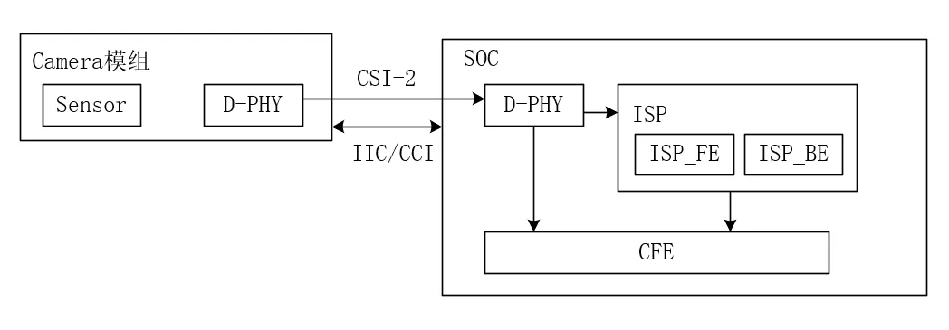
PiSP 摄像头前端 (CFE) 是一个将 CSI-2 接收器与 一个简单的 ISP,称为前端 (FE)。
CFE 有四个 DMA 引擎,可以从四个单独的流写入帧 从 CSI-2 接收到内存。也可以路由其中一个流 直接给 FE 做最少的图片处理,写两个版本 (例如,未缩放和缩小版本)将接收到的帧保存到内存中,并且 提供接收到的帧的统计信息。
FE寄存器参考:https://datasheets.raspberrypi.com/camera/raspberry-pi-image-signal-processor-specification.pdf
FE的示例代码:https://github.com/raspberrypi/libpisp.git
参考资料:https://www.kernel.org/doc/html/latest/admin-guide/media/index.html
https://www.kernel.org/doc/html/latest/userspace-api/media/v4l/v4l2.html
树莓派Linux源码仓库:https://github.com/raspberrypi/linux.git
2.rpl-cfe驱动程序
2.1 raspberrypi camera驱动框图
Raspberry PiSP 摄像头前端 (rp1-cfe) 驱动程序位于 drivers/media/platform/raspberrypi/rp1-cfe 的 Drivers/Media/Platform/RaspberryPi/RP1-CFE 中。它使用 V4L2 API 注册 多个视频采集和输出设备,V4L2 subdev API 注册 接收的 CSI-2 的子设备以及连接视频设备的 FE 使用媒体控制器 (MC) API 实现的单个媒体图。
rp1-cfe 驱动程序注册的媒体拓扑,在此特定 连接到 IMX219 传感器的示例如下:
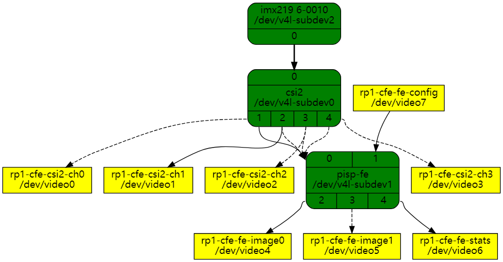
媒体图包含以下视频设备节点:
● rp1-cfe-csi2-ch0:第一个 CSI-2 流的捕获设备
● rp1-cfe-csi2-ch1:第二个 CSI-2 流的捕获设备
● rp1-cfe-csi2-ch2:第三个 CSI-2 流的捕获设备
● rp1-cfe-csi2-ch3:第四个 CSI-2 流的捕获设备
● rp1-cfe-fe-image0:第一个 FE 输出的捕获设备
● rp1-cfe-fe-image1:第二个 FE 输出的捕获设备
● rp1-cfe-fe-stats:用于 FE 统计信息的捕获设备
● rp1-cfe-fe-config:FE 配置的输出设备
rp1-cfe-csi2-chX 捕获设备是普通的 V4L2 捕获设备,它 可用于捕获从 CSI-2 接收的视频帧或元数据。
rp1-cfe-fe-image0 和 rp1-cfe-fe-image1 捕获设备用于写入 将处理的帧保存到内存中。
FE 统计缓冲区的格式由 C 结构定义,每个参数的含义为 在 PiSP 规范文档中进行了描述。pisp_statistics
FE 配置缓冲区的格式由 C 结构定义,每个参数的含义为 在 PiSP 规范文档中进行了描述。
2.2 rpl-cfe驱动架构
rpl-cfe的目录如下:
PS A:\raspberrypi\linux\drivers\media\platform\raspberrypi\rp1_cfe> dir

Mode                 LastWriteTime         Length Name
----                 -------------         ------ ----
-a----          2025/1/7     21:48          65117 cfe.c
-a----          2025/1/7     21:48            941 cfe.h
-a----          2025/1/7     21:48           8298 cfe_fmts.h
-a----          2025/1/7     21:48          17757 csi2.c
-a----          2025/1/7     21:48           2307 csi2.h
-a----          2025/1/7     21:48           5041 dphy.c
-a----          2025/1/7     21:48            452 dphy.h
-a----          2025/1/7     21:48            409 Kconfig
-a----          2025/1/7     21:48            175 Makefile
-a----          2025/1/7     21:48           1548 pisp_common.h
-a----          2025/1/7     21:48          18627 pisp_fe.c
-a----          2025/1/7     21:48           1323 pisp_fe.h
-a----          2025/1/7     21:48           6514 pisp_fe_config.h
-a----          2025/1/7     21:48           1678 pisp_statistics.h
-a----          2025/1/7     21:48           6487 pisp_types.h
PS A:\raspberrypi\linux\drivers\media\platform\raspberrypi\pisp_be> dir

Mode                 LastWriteTime         Length Name
----                 -------------         ------ ----
-a----          2025/1/7     21:48            407 Kconfig
-a----          2025/1/7     21:48            172 Makefile
-a----          2025/1/7     21:48          55988 pisp_be.c
-a----          2025/1/7     21:48          15149 pisp_be_formats.h
从源文件的文件名分析:
| 文件名 | 功能 |
|---|---|
| cfe.c | CSI-2数据流的捕获设备驱动 |
| csi2.c | MIPI-CSI-2的驱动文件 |
| dphy.c | dphy是mipi接口的物理层标准 |
| pisp_fe.c | isp的前端处理(具体可参考背景知识) |
| pisp_be.c | isp的后端处理 |
数据流图:
2.3.1 D-PHY
D-PHY驱动中对外提供了3个接口:
void dphy_probe(struct dphy_data *dphy);
void dphy_start(struct dphy_data *dphy);
void dphy_stop(struct dphy_data *dphy);
static void dw_csi2_host_write(struct dphy_data *dphy, u32 offset, u32 data)
{
	writel(data, dphy->base + offset);
}

....

static void dphy_init(struct dphy_data *dphy)
{
	dw_csi2_host_write(dphy, PHY_RSTZ, 0);
	dw_csi2_host_write(dphy, PHY_SHUTDOWNZ, 0);
	set_tstclk(dphy, 1);
	set_testen(dphy, 0);
	set_tstclr(dphy, 1);
	usleep_range(15, 20);
	set_tstclr(dphy, 0);
	usleep_range(15, 20);

	dphy_set_hsfreqrange(dphy, dphy->dphy_rate);

	usleep_range(5, 10);
	dw_csi2_host_write(dphy, PHY_SHUTDOWNZ, 1);
	usleep_range(5, 10);
	dw_csi2_host_write(dphy, PHY_RSTZ, 1);
}

void dphy_start(struct dphy_data *dphy)
{
	dw_csi2_host_write(dphy, N_LANES, (dphy->active_lanes - 1));
	dphy_init(dphy);
	dw_csi2_host_write(dphy, RESETN, 0xffffffff);
	usleep_range(10, 50);
}

void dphy_stop(struct dphy_data *dphy)
{
	/* Set only one lane (lane 0) as active (ON) */
	dw_csi2_host_write(dphy, N_LANES, 0);
	dw_csi2_host_write(dphy, RESETN, 0);
}

void dphy_probe(struct dphy_data *dphy)
{
	u32 host_ver;
	u8 host_ver_major, host_ver_minor;

	host_ver = dw_csi2_host_read(dphy, VERSION);
	host_ver_major = (u8)((host_ver >> 24) - '0');
	host_ver_minor = (u8)((host_ver >> 16) - '0');
	host_ver_minor = host_ver_minor * 10;
	host_ver_minor += (u8)((host_ver >> 8) - '0');

	dphy_info("DW dphy Host HW v%u.%u\n", host_ver_major, host_ver_minor);
}
2.3.2 CSI-2
CSI-2是一种应用层协议,通过D-PHY这个物理层传输介质来传输。
CSI-2外露了以下接口:
void csi2_isr(struct csi2_device *csi2, bool *sof, bool *eof);
void csi2_set_buffer(struct csi2_device *csi2, unsigned int channel,
		     dma_addr_t dmaaddr, unsigned int stride,
		     unsigned int size);
void csi2_set_compression(struct csi2_device *csi2, unsigned int channel,
			  enum csi2_compression_mode mode, unsigned int shift,
			  unsigned int offset);
void csi2_start_channel(struct csi2_device *csi2, unsigned int channel,
			enum csi2_mode mode, bool auto_arm,
			bool pack_bytes, unsigned int width,
			unsigned int height);
void csi2_stop_channel(struct csi2_device *csi2, unsigned int channel);
void csi2_open_rx(struct csi2_device *csi2);
void csi2_close_rx(struct csi2_device *csi2);
int csi2_init(struct csi2_device *csi2, struct dentry *debugfs);
void csi2_uninit(struct csi2_device *csi2);
以下为csi-2的初始化函数,tx函数和rx函数的实现:
int csi2_init(struct csi2_device *csi2, struct dentry *debugfs)
{
	unsigned int i, ret;

	spin_lock_init(&csi2->errors_lock);

	csi2->dphy.dev = csi2->v4l2_dev->dev;
	dphy_probe(&csi2->dphy);

	debugfs_create_file("csi2_regs", 0444, debugfs, csi2, &csi2_regs_fops);

	if (csi2_track_errors)
		debugfs_create_file("csi2_errors", 0444, debugfs, csi2,
				    &csi2_errors_fops);

	for (i = 0; i < CSI2_NUM_CHANNELS * 2; i++)
		csi2->pad[i].flags = i < CSI2_NUM_CHANNELS ?
				     MEDIA_PAD_FL_SINK : MEDIA_PAD_FL_SOURCE;

	ret = media_entity_pads_init(&csi2->sd.entity, ARRAY_SIZE(csi2->pad),
				     csi2->pad);
	if (ret)
		return ret;

	/* Initialize subdev */
	v4l2_subdev_init(&csi2->sd, &csi2_subdev_ops);
	csi2->sd.entity.function = MEDIA_ENT_F_VID_IF_BRIDGE;
	csi2->sd.entity.ops = &csi2_entity_ops;
	csi2->sd.flags = V4L2_SUBDEV_FL_HAS_DEVNODE;
	csi2->sd.owner = THIS_MODULE;
	snprintf(csi2->sd.name, sizeof(csi2->sd.name), "csi2");

	ret = v4l2_subdev_init_finalize(&csi2->sd);
	if (ret)
		goto err_entity_cleanup;

	ret = v4l2_device_register_subdev(csi2->v4l2_dev, &csi2->sd);
	if (ret) {
		csi2_err("Failed register csi2 subdev (%d)\n", ret);
		goto err_subdev_cleanup;
	}

	return 0;

err_subdev_cleanup:
	v4l2_subdev_cleanup(&csi2->sd);
err_entity_cleanup:
	media_entity_cleanup(&csi2->sd.entity);

	return ret;
}

void csi2_open_rx(struct csi2_device *csi2)
{
	csi2_reg_write(csi2, CSI2_IRQ_MASK,
		       csi2_track_errors ? CSI2_IRQ_MASK_IRQ_ALL : 0);

	dphy_start(&csi2->dphy);

	csi2_reg_write(csi2, CSI2_CTRL,
		       csi2->multipacket_line ? 0 : EOP_IS_EOL);
}

void csi2_close_rx(struct csi2_device *csi2)
{
	dphy_stop(&csi2->dphy);

	csi2_reg_write(csi2, CSI2_IRQ_MASK, 0);
}

static const struct v4l2_subdev_pad_ops csi2_subdev_pad_ops = {
	.init_cfg = csi2_init_cfg,
	.get_fmt = v4l2_subdev_get_fmt,
	.set_fmt = csi2_pad_set_fmt,
	.link_validate = v4l2_subdev_link_validate_default,
};

static const struct media_entity_operations csi2_entity_ops = {
	.link_validate = v4l2_subdev_link_validate,
};

static const struct v4l2_subdev_ops csi2_subdev_ops = {
	.pad = &csi2_subdev_pad_ops,
};
2.3.3 CFE
在树莓派的驱动中,CFE(Camera Front End)是一个重要的概念,它涉及到摄像头模块与树莓派之间的数据传输和处理。
定义:
• CFE 是树莓派摄像头前端,负责将 CSI-2 接收器与一个简单的 ISP(图像信号处理器)连接起来,称为前端(FE)。
• CFE 有四个 DMA 引擎,可以从四个单独的流写入帧从 CSI-2 接收到内存。也可以路由其中一个流直接给 FE 做最少的图片处理,写两个版本(例如,未缩放和缩小版本)将接收到的帧保存到内存中,并且提供接收到的帧的统计信息。
主要功能:
1. 数据传输:
• CFE 通过 CSI-2 接收器接收摄像头模块的图像数据。
• 支持多个数据通道(lane),每个通道可以是 D-PHY 或 C-PHY。
2. DMA 引擎:
• CFE 有四个 DMA 引擎,可以从四个单独的流写入帧到内存。
• 支持将接收到的帧保存到内存中,并且可以生成多个版本(例如,未缩放和缩小版本)。
3. 图像处理:
• CFE 可以将其中一个流直接路由给 FE 进行基本的图像处理。
• 提供接收到的帧的统计信息,用于图像质量控制和调试。
4. V4L2 子设备:
• CFE 使用 V4L2 API 注册多个视频采集和输出设备。
• 使用 V4L2 subdev API 注册接收的 CSI-2 的子设备。
• 使用媒体控制器(MC)API 实现单个媒体图,管理视频设备的连接和数据流。
CFE驱动源码:
const struct cfe_fmt *find_format_by_code(u32 code);
const struct cfe_fmt *find_format_by_pix(u32 pixelformat);
u32 cfe_find_16bit_code(u32 code);
u32 cfe_find_compressed_code(u32 code);
#include <linux/module.h>
#include <linux/platform_device.h>
#include <linux/v4l2-subdev.h>
#include <media/v4l2-ctrls.h>
#include <media/v4l2-device.h>
#include <media/v4l2-subdev.h>

// 初始化cfe设备
static int cfe_probe(struct platform_device *pdev)
{
	struct cfe_device *cfe;
	char debugfs_name[32];
	int ret;

    // 1.分配和初始化cfe_device结构体
	cfe = kzalloc(sizeof(*cfe), GFP_KERNEL);
	if (!cfe)
		return -ENOMEM;

    // 2.将cfe与平台关联起来
	platform_set_drvdata(pdev, cfe);

    // 3.管理cfe设备的引用计数
	kref_init(&cfe->kref);
	cfe->pdev = pdev;
	cfe->fe_csi2_channel = -1;
	spin_lock_init(&cfe->state_lock);

    // 4.映射CSI-2,D-PHY,MIPI配置和FE寄存器
	cfe->csi2.base = devm_platform_ioremap_resource(pdev, 0);
	if (IS_ERR(cfe->csi2.base)) {
		dev_err(&pdev->dev, "Failed to get dma io block\n");
		ret = PTR_ERR(cfe->csi2.base);
		goto err_cfe_put;
	}

    // D-PHY
	cfe->csi2.dphy.base = devm_platform_ioremap_resource(pdev, 1);
	if (IS_ERR(cfe->csi2.dphy.base)) {
		dev_err(&pdev->dev, "Failed to get host io block\n");
		ret = PTR_ERR(cfe->csi2.dphy.base);
		goto err_cfe_put;
	}

    // mipi配置
	cfe->mipi_cfg_base = devm_platform_ioremap_resource(pdev, 2);
	if (IS_ERR(cfe->mipi_cfg_base)) {
		dev_err(&pdev->dev, "Failed to get mipi cfg io block\n");
		ret = PTR_ERR(cfe->mipi_cfg_base);
		goto err_cfe_put;
	}

    // fe配置
	cfe->fe.base = devm_platform_ioremap_resource(pdev, 3);
	if (IS_ERR(cfe->fe.base)) {
		dev_err(&pdev->dev, "Failed to get pisp fe io block\n");
		ret = PTR_ERR(cfe->fe.base);
		goto err_cfe_put;
	}

	ret = platform_get_irq(pdev, 0);
	if (ret <= 0) {
		dev_err(&pdev->dev, "No IRQ resource\n");
		ret = -EINVAL;
		goto err_cfe_put;
	}

	ret = devm_request_irq(&pdev->dev, ret, cfe_isr, 0, "rp1-cfe", cfe);
	if (ret) {
		dev_err(&pdev->dev, "Unable to request interrupt\n");
		ret = -EINVAL;
		goto err_cfe_put;
	}

	ret = dma_set_mask_and_coherent(&pdev->dev, DMA_BIT_MASK(64));
	if (ret) {
		dev_err(&pdev->dev, "DMA enable failed\n");
		goto err_cfe_put;
	}

	/* TODO: Enable clock only when running. */
	cfe->clk = devm_clk_get(&pdev->dev, NULL);
	if (IS_ERR(cfe->clk))
		return dev_err_probe(&pdev->dev, PTR_ERR(cfe->clk),
				     "clock not found\n");

	cfe->mdev.dev = &pdev->dev;
	cfe->mdev.ops = &cfe_media_device_ops;
	strscpy(cfe->mdev.model, CFE_MODULE_NAME, sizeof(cfe->mdev.model));
	strscpy(cfe->mdev.serial, "", sizeof(cfe->mdev.serial));
	snprintf(cfe->mdev.bus_info, sizeof(cfe->mdev.bus_info), "platform:%s",
		 dev_name(&pdev->dev));

	media_device_init(&cfe->mdev);

	cfe->v4l2_dev.mdev = &cfe->mdev;

	ret = v4l2_device_register(&pdev->dev, &cfe->v4l2_dev);
	if (ret) {
		cfe_err("Unable to register v4l2 device.\n");
		goto err_cfe_put;
	}

	snprintf(debugfs_name, sizeof(debugfs_name), "rp1-cfe:%s",
		 dev_name(&pdev->dev));
	cfe->debugfs = debugfs_create_dir(debugfs_name, NULL);
	debugfs_create_file("format", 0444, cfe->debugfs, cfe, &format_fops);
	debugfs_create_file("regs", 0444, cfe->debugfs, cfe,
			    &mipi_cfg_regs_fops);

	/* Enable the block power domain */
	pm_runtime_enable(&pdev->dev);

	ret = pm_runtime_resume_and_get(&cfe->pdev->dev);
	if (ret)
		goto err_runtime_disable;

	cfe->csi2.v4l2_dev = &cfe->v4l2_dev;
	ret = csi2_init(&cfe->csi2, cfe->debugfs);
	if (ret) {
		cfe_err("Failed to init csi2 (%d)\n", ret);
		goto err_runtime_put;
	}

	cfe->fe.v4l2_dev = &cfe->v4l2_dev;
	ret = pisp_fe_init(&cfe->fe, cfe->debugfs);
	if (ret) {
		cfe_err("Failed to init pisp fe (%d)\n", ret);
		goto err_csi2_uninit;
	}

	cfe->mdev.hw_revision = cfe->fe.hw_revision;
	ret = media_device_register(&cfe->mdev);
	if (ret < 0) {
		cfe_err("Unable to register media-controller device.\n");
		goto err_pisp_fe_uninit;
	}

	ret = of_cfe_connect_subdevs(cfe);
	if (ret) {
		cfe_err("Failed to connect subdevs\n");
		goto err_media_unregister;
	}

	pm_runtime_put(&cfe->pdev->dev);

	return 0;

err_media_unregister:
	media_device_unregister(&cfe->mdev);
err_pisp_fe_uninit:
	pisp_fe_uninit(&cfe->fe);
err_csi2_uninit:
	csi2_uninit(&cfe->csi2);
err_runtime_put:
	pm_runtime_put(&cfe->pdev->dev);
err_runtime_disable:
	pm_runtime_disable(&pdev->dev);
	debugfs_remove(cfe->debugfs);
	v4l2_device_unregister(&cfe->v4l2_dev);
// 释放已分配的资源
err_cfe_put:
	cfe_put(cfe);

	return ret;
}


static int cfe_start_streaming(struct vb2_queue *vq, unsigned int count)
{
	struct v4l2_mbus_config mbus_config = { 0 };
	struct cfe_node *node = vb2_get_drv_priv(vq);
	struct cfe_device *cfe = node->cfe;
	int ret;

	cfe_dbg("%s: [%s] begin.\n", __func__, node_desc[node->id].name);

	if (!check_state(cfe, NODE_ENABLED, node->id)) {
		cfe_err("%s node link is not enabled.\n",
			node_desc[node->id].name);
		ret = -EINVAL;
		goto err_streaming;
	}

	ret = pm_runtime_resume_and_get(&cfe->pdev->dev);
	if (ret < 0) {
		cfe_err("pm_runtime_resume_and_get failed\n");
		goto err_streaming;
	}

	/* When using the Frontend, we must enable the FE_CONFIG node. */
	if (is_fe_enabled(cfe) &&
	    !check_state(cfe, NODE_ENABLED, cfe->node[FE_CONFIG].id)) {
		cfe_err("FE enabled, but FE_CONFIG node is not\n");
		ret = -EINVAL;
		goto err_pm_put;
	}

	ret = media_pipeline_start(&node->pad, &cfe->pipe);
	if (ret < 0) {
		cfe_err("Failed to start media pipeline: %d\n", ret);
		goto err_pm_put;
	}

	clear_state(cfe, FS_INT | FE_INT, node->id);
	set_state(cfe, NODE_STREAMING, node->id);
	node->fs_count = 0;
	cfe_start_channel(node);

	if (!test_all_nodes(cfe, NODE_ENABLED, NODE_STREAMING)) {
		cfe_dbg("Not all nodes are set to streaming yet!\n");
		return 0;
	}

	cfg_reg_write(cfe, MIPICFG_CFG, MIPICFG_CFG_SEL_CSI);
	cfg_reg_write(cfe, MIPICFG_INTE, MIPICFG_INT_CSI_DMA | MIPICFG_INT_PISP_FE);

	ret = v4l2_subdev_call(cfe->sensor, pad, get_mbus_config, 0,
			       &mbus_config);
	if (ret < 0 && ret != -ENOIOCTLCMD) {
		cfe_err("g_mbus_config failed\n");
		goto err_pm_put;
	}

	cfe->csi2.dphy.active_lanes = mbus_config.bus.mipi_csi2.num_data_lanes;
	if (!cfe->csi2.dphy.active_lanes)
		cfe->csi2.dphy.active_lanes = cfe->csi2.dphy.max_lanes;
	if (cfe->csi2.dphy.active_lanes > cfe->csi2.dphy.max_lanes) {
		cfe_err("Device has requested %u data lanes, which is >%u configured in DT\n",
			cfe->csi2.dphy.active_lanes, cfe->csi2.dphy.max_lanes);
		ret = -EINVAL;
		goto err_disable_cfe;
	}

	cfe_dbg("Configuring CSI-2 block - %u data lanes\n", cfe->csi2.dphy.active_lanes);
	cfe->csi2.dphy.dphy_rate = sensor_link_rate(cfe) / 1000000UL;
	csi2_open_rx(&cfe->csi2);

	cfe_dbg("Starting sensor streaming\n");
	ret = v4l2_subdev_call(cfe->sensor, video, s_stream, 1);
	if (ret < 0) {
		cfe_err("stream on failed in subdev\n");
		goto err_disable_cfe;
	}

	cfe_dbg("%s: [%s] end.\n", __func__, node_desc[node->id].name);

	return 0;

err_disable_cfe:
	csi2_close_rx(&cfe->csi2);
	cfe_stop_channel(node, true);
	media_pipeline_stop(&node->pad);
err_pm_put:
	pm_runtime_put(&cfe->pdev->dev);
err_streaming:
	cfe_return_buffers(node, VB2_BUF_STATE_QUEUED);
	clear_state(cfe, NODE_STREAMING, node->id);

	return ret;
}

static void cfe_stop_streaming(struct vb2_queue *vq)
{
	struct cfe_node *node = vb2_get_drv_priv(vq);
	struct cfe_device *cfe = node->cfe;
	unsigned long flags;
	bool fe_stop;

	cfe_dbg("%s: [%s] begin.\n", __func__, node_desc[node->id].name);

	spin_lock_irqsave(&cfe->state_lock, flags);
	fe_stop = is_fe_enabled(cfe) &&
		  test_all_nodes(cfe, NODE_ENABLED, NODE_STREAMING);

	cfe->job_ready = false;
	clear_state(cfe, NODE_STREAMING, node->id);
	spin_unlock_irqrestore(&cfe->state_lock, flags);

	cfe_stop_channel(node, fe_stop);

	if (!test_any_node(cfe, NODE_STREAMING)) {
		/* Stop streaming the sensor and disable the peripheral. */
		if (v4l2_subdev_call(cfe->sensor, video, s_stream, 0) < 0)
			cfe_err("stream off failed in subdev\n");

		csi2_close_rx(&cfe->csi2);

		cfg_reg_write(cfe, MIPICFG_INTE, 0);
	}

	media_pipeline_stop(&node->pad);

	/* Clear all queued buffers for the node */
	cfe_return_buffers(node, VB2_BUF_STATE_ERROR);

	pm_runtime_put(&cfe->pdev->dev);

	cfe_dbg("%s: [%s] end.\n", __func__, node_desc[node->id].name);
}

static int cfe_remove(struct platform_device *pdev)
{
    struct cfe_device *cfe = platform_get_drvdata(pdev);

    kref_put(&cfe->kref, cfe_release);
    return 0;
}


static const struct vb2_ops cfe_video_qops = {
	.wait_prepare = vb2_ops_wait_prepare,
	.wait_finish = vb2_ops_wait_finish,
	.queue_setup = cfe_queue_setup,
	.buf_prepare = cfe_buffer_prepare,
	.buf_queue = cfe_buffer_queue,
	.start_streaming = cfe_start_streaming,
	.stop_streaming = cfe_stop_streaming,
};

// 此函数用于创建cfe与csi或isp_fe的连接pad(垫)
static int cfe_link_node_pads(struct cfe_device *cfe)
{
	unsigned int i, source_pad = 0;
	int ret;

	for (i = 0; i < CSI2_NUM_CHANNELS; i++) {
		struct cfe_node *node = &cfe->node[i];

		if (!check_state(cfe, NODE_REGISTERED, i))
			continue;

		/* Find next source pad */
		while (source_pad < cfe->sensor->entity.num_pads &&
		       !(cfe->sensor->entity.pads[source_pad].flags &
							MEDIA_PAD_FL_SOURCE))
			source_pad++;

		if (source_pad < cfe->sensor->entity.num_pads) {
			/* Sensor -> CSI2 */
			ret = media_create_pad_link(&cfe->sensor->entity, source_pad,
						    &cfe->csi2.sd.entity, i,
						    MEDIA_LNK_FL_IMMUTABLE |
						    MEDIA_LNK_FL_ENABLED);
			if (ret)
				return ret;

			/* Dealt with that source_pad, look at the next one next time */
			source_pad++;
		}

		/* CSI2 channel # -> /dev/video# */
		ret = media_create_pad_link(&cfe->csi2.sd.entity,
					    node_desc[i].link_pad,
					    &node->video_dev.entity, 0, 0);
		if (ret)
			return ret;

		if (node_supports_image(node)) {
			/* CSI2 channel # -> FE Input */
			ret = media_create_pad_link(&cfe->csi2.sd.entity,
						    node_desc[i].link_pad,
						    &cfe->fe.sd.entity,
						    FE_STREAM_PAD, 0);
			if (ret)
				return ret;
		}
	}

	for (; i < NUM_NODES; i++) {
		struct cfe_node *node = &cfe->node[i];
		struct media_entity *src, *dst;
		unsigned int src_pad, dst_pad;

		if (node_desc[i].pad_flags & MEDIA_PAD_FL_SINK) {
			/* FE -> /dev/video# */
			src = &cfe->fe.sd.entity;
			src_pad = node_desc[i].link_pad;
			dst = &node->video_dev.entity;
			dst_pad = 0;
		} else {
			/* /dev/video# -> FE */
			dst = &cfe->fe.sd.entity;
			dst_pad = node_desc[i].link_pad;
			src = &node->video_dev.entity;
			src_pad = 0;
		}

		ret = media_create_pad_link(src, src_pad, dst, dst_pad, 0);
		if (ret)
			return ret;
	}

	return 0;
}

static const struct of_device_id cfe_of_match[] = {
	{ .compatible = "raspberrypi,rp1-cfe" },
	{ /* sentinel */ },
};
MODULE_DEVICE_TABLE(of, cfe_of_match);

static struct platform_driver cfe_driver = {
	.probe		= cfe_probe,
	.remove		= cfe_remove,
	.driver = {
		.name	= CFE_MODULE_NAME,
		.of_match_table = cfe_of_match,
		.pm = &cfe_pm_ops,
	},
};

module_platform_driver(cfe_driver);

MODULE_AUTHOR("Naushir Patuck <naush@raspberrypi.com>");
MODULE_DESCRIPTION("RP1 Camera Front End driver");
MODULE_LICENSE("GPL");
MODULE_VERSION(CFE_VERSION);
2.3.4 ISP_FE
ISP_FE是图像信号处理前端
void pisp_fe_isr(struct pisp_fe_device *fe, bool *sof, bool *eof);
int pisp_fe_validate_config(struct pisp_fe_device *fe,
			    struct pisp_fe_config *cfg,
			    struct v4l2_format const *f0,
			    struct v4l2_format const *f1);
void pisp_fe_submit_job(struct pisp_fe_device *fe, struct vb2_buffer **vb2_bufs,
			struct pisp_fe_config *cfg);
void pisp_fe_start(struct pisp_fe_device *fe);
void pisp_fe_stop(struct pisp_fe_device *fe);
int pisp_fe_init(struct pisp_fe_device *fe, struct dentry *debugfs);
void pisp_fe_uninit(struct pisp_fe_device *fe);
int pisp_fe_init(struct pisp_fe_device *fe, struct dentry *debugfs)
{
	int ret;

	debugfs_create_file("pisp_regs", 0444, debugfs, fe, &pisp_regs_fops);

	fe->hw_revision = pisp_fe_reg_read(fe, FE_VERSION);
	pisp_fe_info("PiSP FE HW v%u.%u\n",
		     (fe->hw_revision >> 24) & 0xff,
		     (fe->hw_revision >> 20) & 0x0f);

	fe->pad[FE_STREAM_PAD].flags =
		MEDIA_PAD_FL_SINK | MEDIA_PAD_FL_MUST_CONNECT;
	fe->pad[FE_CONFIG_PAD].flags = MEDIA_PAD_FL_SINK;
	fe->pad[FE_OUTPUT0_PAD].flags = MEDIA_PAD_FL_SOURCE;
	fe->pad[FE_OUTPUT1_PAD].flags = MEDIA_PAD_FL_SOURCE;
	fe->pad[FE_STATS_PAD].flags = MEDIA_PAD_FL_SOURCE;

	ret = media_entity_pads_init(&fe->sd.entity, ARRAY_SIZE(fe->pad),
				     fe->pad);
	if (ret)
		return ret;

	/* Initialize subdev */
	v4l2_subdev_init(&fe->sd, &pisp_fe_subdev_ops);
	fe->sd.entity.function = MEDIA_ENT_F_PROC_VIDEO_SCALER;
	fe->sd.entity.ops = &pisp_fe_entity_ops;
	fe->sd.entity.name = "pisp-fe";
	fe->sd.flags = V4L2_SUBDEV_FL_HAS_DEVNODE;
	fe->sd.owner = THIS_MODULE;
	snprintf(fe->sd.name, sizeof(fe->sd.name), "pisp-fe");

	ret = v4l2_subdev_init_finalize(&fe->sd);
	if (ret)
		goto err_entity_cleanup;

	ret = v4l2_device_register_subdev(fe->v4l2_dev, &fe->sd);
	if (ret) {
		pisp_fe_err("Failed register pisp fe subdev (%d)\n", ret);
		goto err_subdev_cleanup;
	}

	/* Must be in IDLE state (STATUS == 0) here. */
	WARN_ON(pisp_fe_reg_read(fe, FE_STATUS));

	return 0;

err_subdev_cleanup:
	v4l2_subdev_cleanup(&fe->sd);
err_entity_cleanup:
	media_entity_cleanup(&fe->sd.entity);

	return ret;
}

void pisp_fe_start(struct pisp_fe_device *fe)
{
	pisp_fe_reg_write(fe, FE_CONTROL, FE_CONTROL_RESET);
	pisp_fe_reg_write(fe, FE_INT_STATUS, ~0);
	pisp_fe_reg_write(fe, FE_INT_EN, FE_INT_EOF | FE_INT_SOF | FE_INT_LINES0 | FE_INT_LINES1);
	fe->inframe_count = 0;
}

void pisp_fe_stop(struct pisp_fe_device *fe)
{
	pisp_fe_reg_write(fe, FE_INT_EN, 0);
	pisp_fe_reg_write(fe, FE_CONTROL, FE_CONTROL_ABORT);
	usleep_range(1000, 2000);
	WARN_ON(pisp_fe_reg_read(fe, FE_STATUS));
	pisp_fe_reg_write(fe, FE_INT_STATUS, ~0);
}
背景知识
ISP
在图像信号处理(ISP)领域,ISP_FE和 ISP_BE分别代表图像信号处理的前端(Front End)和后端(Back End)。以下是它们的详细解释:
ISP_FE(图像信号处理前端)
定义:
ISP_FE是图像信号处理流水线中前端部分,主要负责从图像传感器接收原始图像数据(通常是 Bayer 格式)并进行初步处理。
主要功能:
• 图像裁剪(Crop):对输入图像进行裁剪,去除不需要的边缘部分。
• 坏点校正(Defect Pixel Correction,DPC):检测和校正图像中的坏点。
• 黑电平校正(Black Level Compensation,BLC):校正图像的黑电平,提高图像质量。
• 镜头阴影校正(Lens Shading Correction,LSC):校正由于镜头光学特性导致的图像阴影。
• 自动曝光控制(Auto Exposure Control,AEC):根据环境光线自动调整曝光参数,以获得最佳图像亮度。
• 自动白平衡(Auto White Balance,AWB):自动调整图像的白平衡,使图像颜色更自然。
ISP_BE(图像信号处理后端)
定义:
ISP_BE是图像信号处理流水线中后端部分,主要负责对前端处理后的图像数据进行进一步的处理,生成最终的输出图像(通常是 YUV 或 RGB 格式)。
主要功能:
• 去噪(Noise Reduction,NR):在 Bayer 域或 RGB 域进行去噪处理,减少图像噪声。
• 色彩校正(Color Correction Matrix,CCM):通过矩阵变换调整图像的色彩平衡。
• 伽马校正(Gamma Correction):调整图像的伽马曲线,改善图像的对比度和亮度。
• 锐化(Sharpening):增强图像的边缘,提高图像的清晰度。
• 动态范围压缩(Dynamic Range Compression,DRC):压缩图像的动态范围,使图像在不同光照条件下都能保持良好的视觉效果。
• 多帧合成宽动态(Multi-Frame Wide Dynamic Range,WDR):通过多帧合成技术,提高图像在高动态范围场景下的表现。
• 色彩空间转换(Color Space Conversion):将图像从 Bayer 格式转换为 YUV 或 RGB 格式,以便后续处理和显示。
示例架构
以下是一个典型的 ISP 架构示例,展示了 ISP_FE和 ISP_BE的位置和功能:
图像传感器 (Sensor) --> ISP_FE --> ISP_BE --> 输出图像 (YUV/RGB)
• ISP_FE:
• 接收 Bayer 格式的原始图像数据。
• 进行裁剪、坏点校正、黑电平校正、镜头阴影校正等初步处理。
• 输出处理后的 Bayer 图像数据。
• ISP_BE:
• 接收处理后的 Bayer 图像数据。
• 进行去噪、色彩校正、伽马校正、锐化、动态范围压缩等高级处理。
• 输出最终的 YUV 或 RGB 图像数据。
总结
• ISP_FE:主要负责从图像传感器接收原始图像数据并进行初步处理。
• ISP_BE:主要负责对初步处理后的图像数据进行进一步的处理,生成最终的输出图像。
通过这种分工,ISP 能够高效地处理图像数据,提供高质量的图像输出。
CSI-2,C-PHY,D-PHY
D-PHY:
-
D-PHY 是 MIPI 接口的一种物理层标准,主要用于摄像头(CSI)和显示屏(DSI)的数据传输。
-
D 是罗马数字中的 500,表示 D-PHY 最初设计目标是支持 500 Mbits/s 的数据传输速率。
C-PHY:
• C-PHY 是 MIPI 接口的另一种物理层标准,旨在提供更高的数据传输速率,适用于高带宽应用。
• C 代表 Channel-limited,表示 C-PHY 适用于通道受限的应用场景。
CSI-2:
- CSI-2 是 MIPI 接口的一种应用层协议,主要用于摄像头模块与处理器之间的高速数据传输。
- CSI-2 定义了数据传输的格式、协议和控制机制,确保摄像头采集的图像数据能够高效、准确地传输到处理器。
| 特性 | D-PHY | C-PHY | CSI-2 |
|---|---|---|---|
| 类型 | 物理层标准 | 物理层标准 | 应用层协议 |
| 主要功能 | 数据传输的物理介质定义 | 数据传输的物理介质定义 | 数据传输的格式和控制机制 |
| 信号传输 | 差分信号对,每条 lane 两根线 | 三相信号 | 定义数据包格式和传输协议 |
| 时钟支持 | 独立时钟线 | C-PHY 没有单独的时钟线,时钟信号嵌入在数据传输的时序中,减少了引脚数量 | 通过 LLP 和 Lane Management 管理时钟 |
| 传输速率 | 最高 1.5 Gbps/通道 | 高达 2.5 Gbps | 依赖于物理层(D-PHY 或 C-PHY) |
| 数据线配置 | 1/2/4 条数据 lane | 三条信号线 | 多通道数据传输,每个通道可以是 D-PHY 或 C-PHY |
| 应用场景 | 摄像头和显示屏的数据传输 | 高端显示器、相机模块 | 摄像头模块与处理器之间的数据传输 |
| 控制接口 | 无 | 无 | 包含 CCI(基于 I2C) |

 浙公网安备 33010602011771号