每天学习亿点点9.27 d3d12 rootparameter 和range以及渲染管线再探究
1.rootparameter和range
在之前学习d3d12基础的时候
对于

这样几行代码我始终没有搞明白是什么意思,range到底是什么意思, root parameter 到底是什么意思. 在root signature里面到底是什么结构.

虽然在rootSignature里面看得出来初始化这个object只需要rootParameter, 但是资源到底是如何绑定却有点无法理解.
直到我看到了msdn里的几张图, 并且自己稍微修改了一下代码, 试验并验证了我的想法.

pipeline图
即整体的渲染图和一个descriptor table的结构示例图

descriptor table
再加上在 stack overflow看到的一个回答:
关于渲染管线的register的数量限制
-
D3D11_COMMONSHADER_INPUT_RESOURCE_REGISTER_COUNT (which is t) = 128
-
D3D11_COMMONSHADER_SAMPLER_SLOT_COUNT (which is s) = 16
-
D3D11_COMMONSHADER_CONSTANT_BUFFER_HW_SLOT_COUNT (which is b) = 15 but one is reserved to eventually store some constant data from shaders (if you have a static const large array for example)
The u case is different, as it depends on Feature Level (and tbh is a vendor/os version mess) :
-
D3D11_FEATURE_LEVEL_11_1 or greater, this is 64 slots
-
D3D11_FEATURE_LEVEL_11 : It will always be 8 (but some cards/driver eventually support 64, you need at least windows 8 for it (It might also be available in windows 7 with some platform update too). I do not recall a way to test if 64 is supported (many nvidia in their 700 range do for example).
-
D3D11_FEATURE_LEVEL_10_1 : either 0 or 1, there's a way to check is compute is supported
虽然这是一个D3D11的feature但是D3D12也差不多.
于是我脑海里就有了一个更加清晰的图景了.
下面就是我画的图:
其实我们完全可以把渲染管线理解成一个超大的函数体, 它分为10个步骤, 其实就相当于10步而已,但其实都是在一个函数体的一部分, 既然是函数体那么必然是有参数进来的.
理解成一个函数体还不够我们还要在硬件上理解,它实际上是有很多固定的信息通道的,就比如register. 但是每个渲染步骤的时候不可能需要用到所有的register而且一般情况也用不了太多register, 所以需要对register的使用进行组合.
以上图为例我们要做一个能旋转带贴图的正方体,这个时候就需要用四种资源: vertex 资源, constant buffer资源, 贴图资源, sampler 资源
由于cbv和srv可以放在一个heap里我们就直接把他们全部创建在一切就完事, sampler单独放一个.
range的作用其实就是告诉我们要使用哪些范围的register(r0到ri),这个才是range真正的含义.
其次root parameter其实就是这个函数体的参数了,也就如下面的代码所示
struct input1
{
b0,b1
}
struct input2
{
s0
}
void RenderingPipeline(input1, input2);
那么知道了要用哪些register那么,每次渲染不同的物体时候,需要的贴图不一样. 如何进行实际的数据连接呢?
这里就用到了
m_commandList->SetGraphicsRootDescriptorTable(0, m_cbvHeap->GetGPUDescriptorHandleForHeapStart());
这么一句代码了。这里其实就是真正的将所有descriptor和参数进行的关联,也即和资源进行了一一映射.
需要说明的一点的是,parameter只管顺序,不管交叉对应的,所以descriptor在heap里的排布顺序一定要和parameter保持一致,不然会出现问题的.
2. 渲染管线再探究
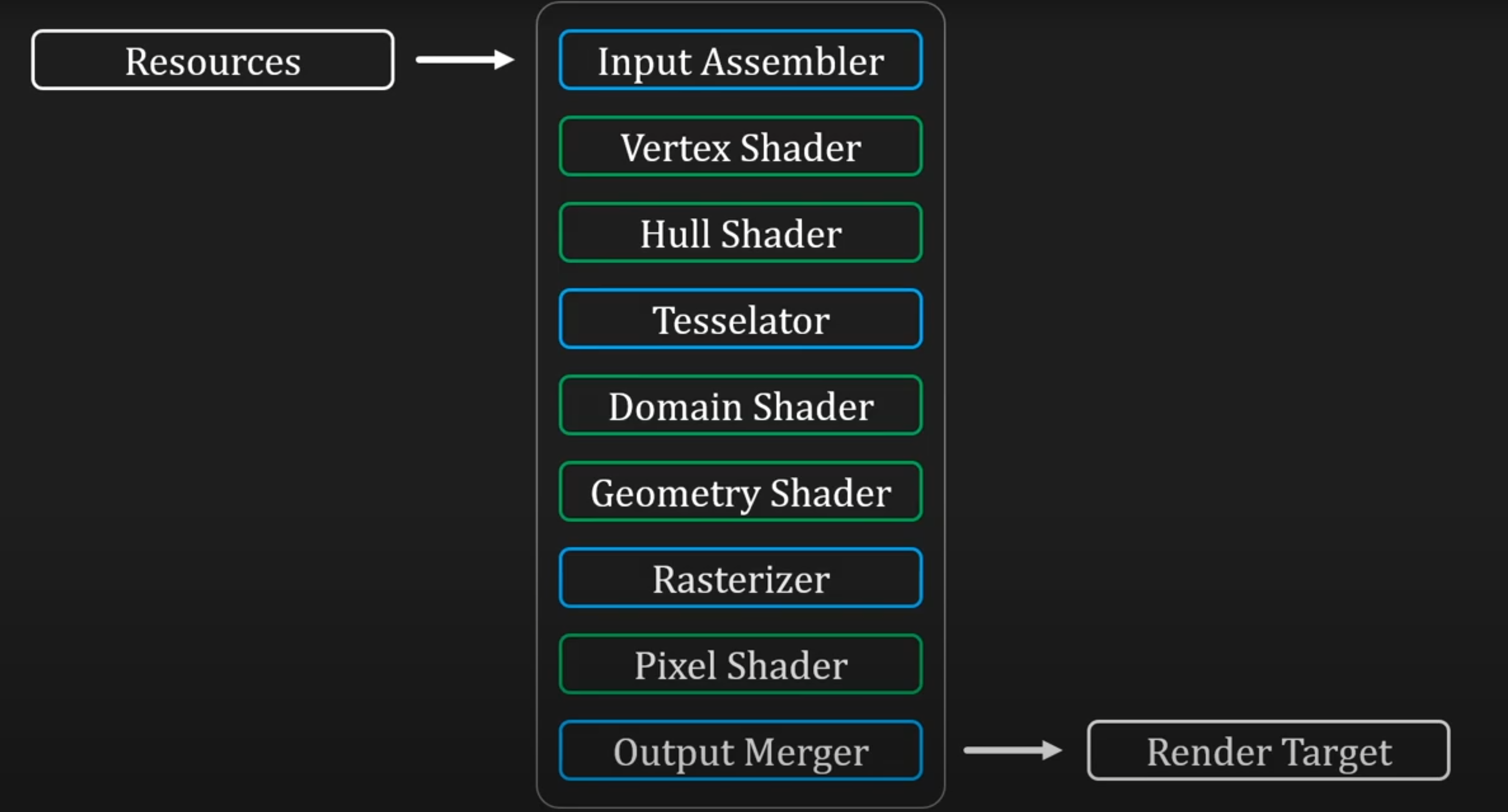
图中绿色的部分就是拥有完全控制权的阶段,蓝色则是只有部分控制权的阶段.
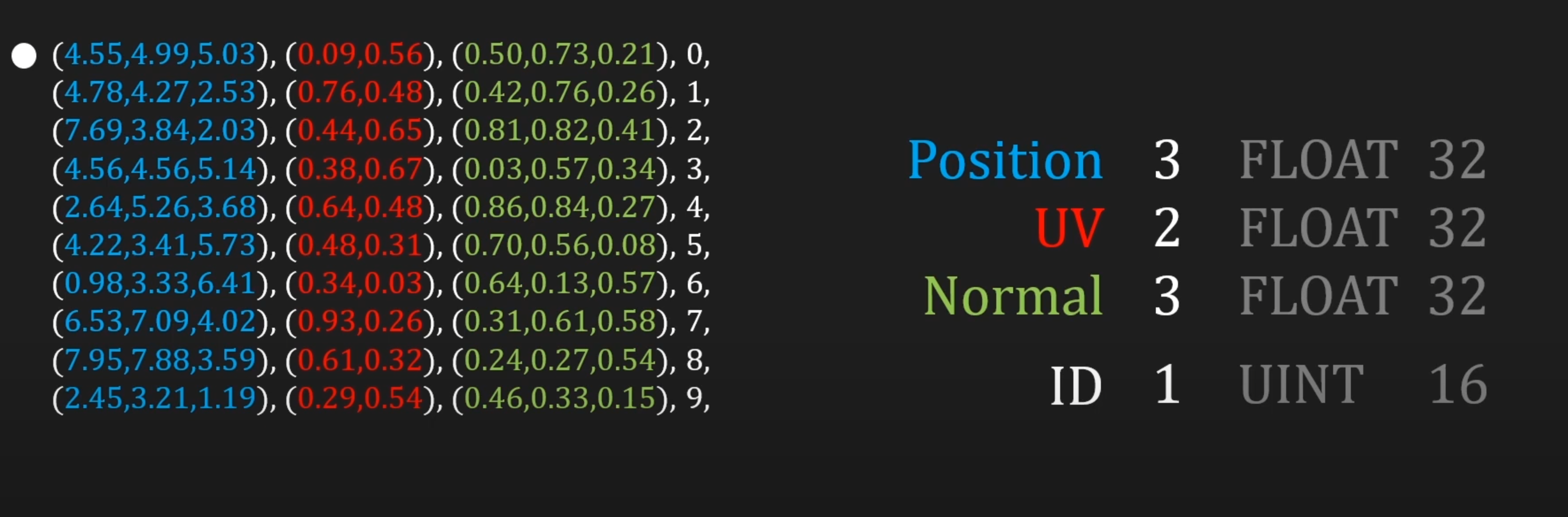
1.input assembler 识别出所有要画的primitive
The Input Assembler (IA) stage supplies primitive and adjacency data to the pipeline, such as triangles, lines and points, including semantics IDs to help make shaders more efficient by reducing processing to primitives that haven't already been processed.
-
Input
Primitive data (triangles, lines, and/or points), from user-filled buffers in memory. And possibly adjacency data. A triangle would be 3 vertices for each triangle and possibly 3 vertices for adjacency data per triangle. -
Output
Primitives with attached system-generated values (such as a primitive ID, an instance ID, or a vertex ID).
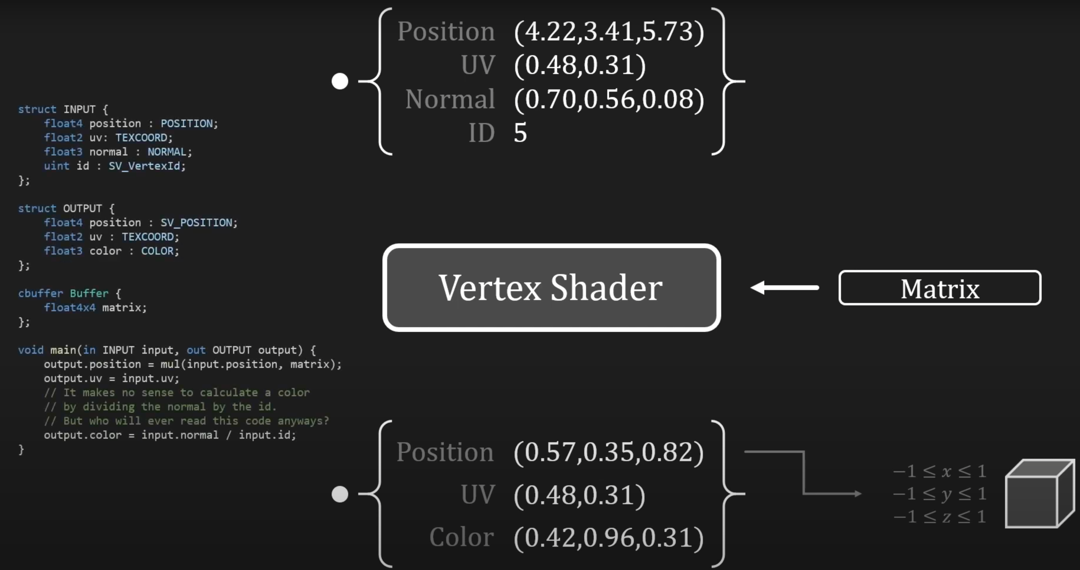
2. Vertex Shader 所有primitive变换到一个2x2x2的正方体中
The Vertex Shader (VS) stage processes vertices, typically performing operations such as transformations, skinning, and lighting. A vertex shader takes a single input vertex and produces a single output vertex. Individual per-vertex operations, such as Transformations, Skinning, Morphing and Per-vertex lighting.
-
Input
A single vertex, with VertexID and InstanceID system-generated values. Each vertex shader input vertex can be comprised of up to 16 32-bit vectors (up to 4 components each). -
Output
A single vertex. Each output vertex can be comprised of as many as 16 32-bit 4-component vectors.
3. Hull shader
The Hull Shader (HS) stage is one of the tessellation stages, which efficiently break up a single surface of a model into many triangles. A hull shader is invoked once per patch, and it transforms input control points that define a low-order surface into control points that make up a patch. It also does some per-patch calculations to provide data for the Tessellator (TS) stage and the Domain Shader (DS) stage.
-
Input
Between 1 and 32 input control points, which together define a low-order surface.输入的控制点 -
Output
Between 1 and 32 output control points, which together make up a patch. The hull shader declares the state for the Tessellator (TS) stage, including the number of control points, the type of patch face, and the type of partitioning to use when tessellating. -
输出一堆控制点, 细分权重, 常量给domain shader
-
输出一堆细分权重, 类型给tessellator
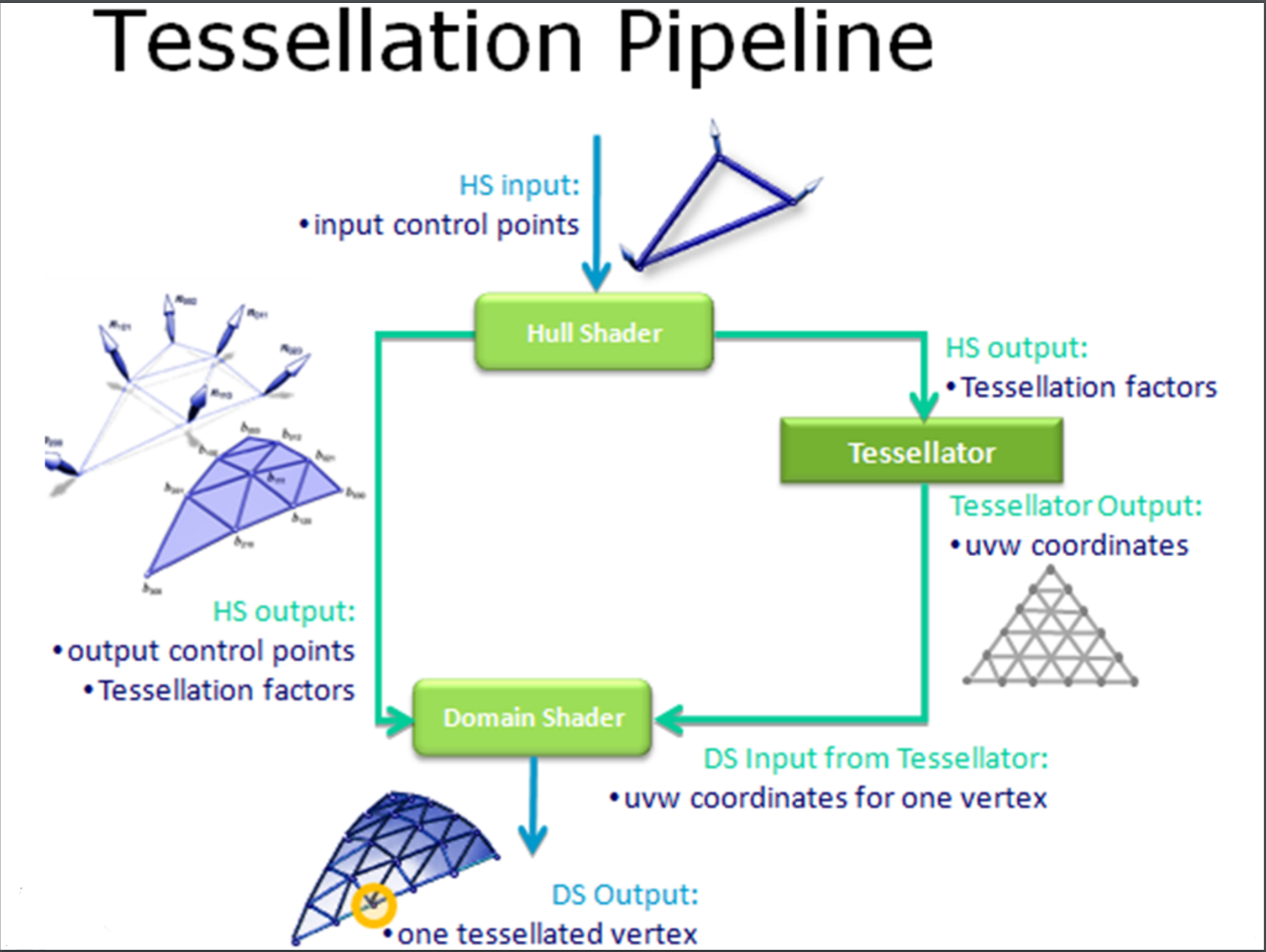
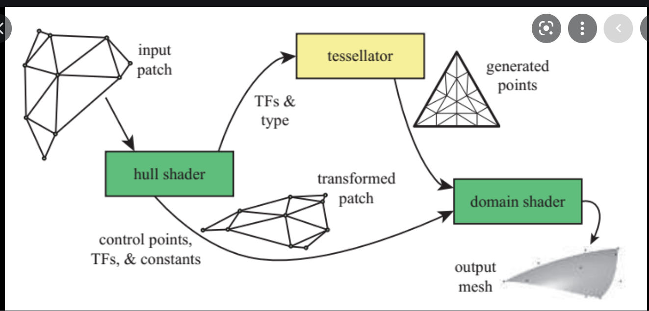
4.Tesselator stage 根据细分权重和类型拆成一堆uvw vertex (这些坐标其实都是平面上的, 确定三维空间坐标需要进一步在domain shader中进行插值计算), uvw其实和三大变换的原理类似, 纹理也有纹理变换(缩放,平移etc), 多加一个w可以把变换写成矩阵, 输出每一个vertex
The Tessellator (TS) stage creates a sampling pattern of the domain that represents the geometry patch and generates a set of smaller objects (triangles, points, or lines) that connect these samples.
-
Input
The tessellator operates once per patch using the tessellation factors (which specify how finely the domain will be tessellated) and the type of partitioning (which specifies the algorithm used to slice up a patch) that are passed in from the hull-shader stage. -
Output
The tessellator outputs uv (and optionally w) coordinates and the surface topology to the domain-shader stage.
5.Domain Shader 得到hull shader增多的控制点和拆好了的vertex, 重新计算每一个vertex的真实位置
The Domain Shader (DS) stage calculates the vertex position of a subdivided point in the output patch; it calculates the vertex position that corresponds to each domain sample. A domain shader is run once per tessellator stage output point and has read-only access to the hull shader output patch and output patch constants, and the tessellator stage output UV coordinates.
-
Input
A domain shader consumes output control points from the Hull Shader (HS) stage. The hull shader outputs include: Control points, Patch constant data, and Tessellation factors (the tessellation factors can include the values used by the fixed-function tessellator as well as the raw values - before rounding by integer tessellation - which facilitates geomorphing, for example). A domain shader is invoked once per output coordinate from the Tessellator (TS) stage. -
Output
The Domain Shader (DS) stage outputs the vertex position of a subdivided point in the output patch. 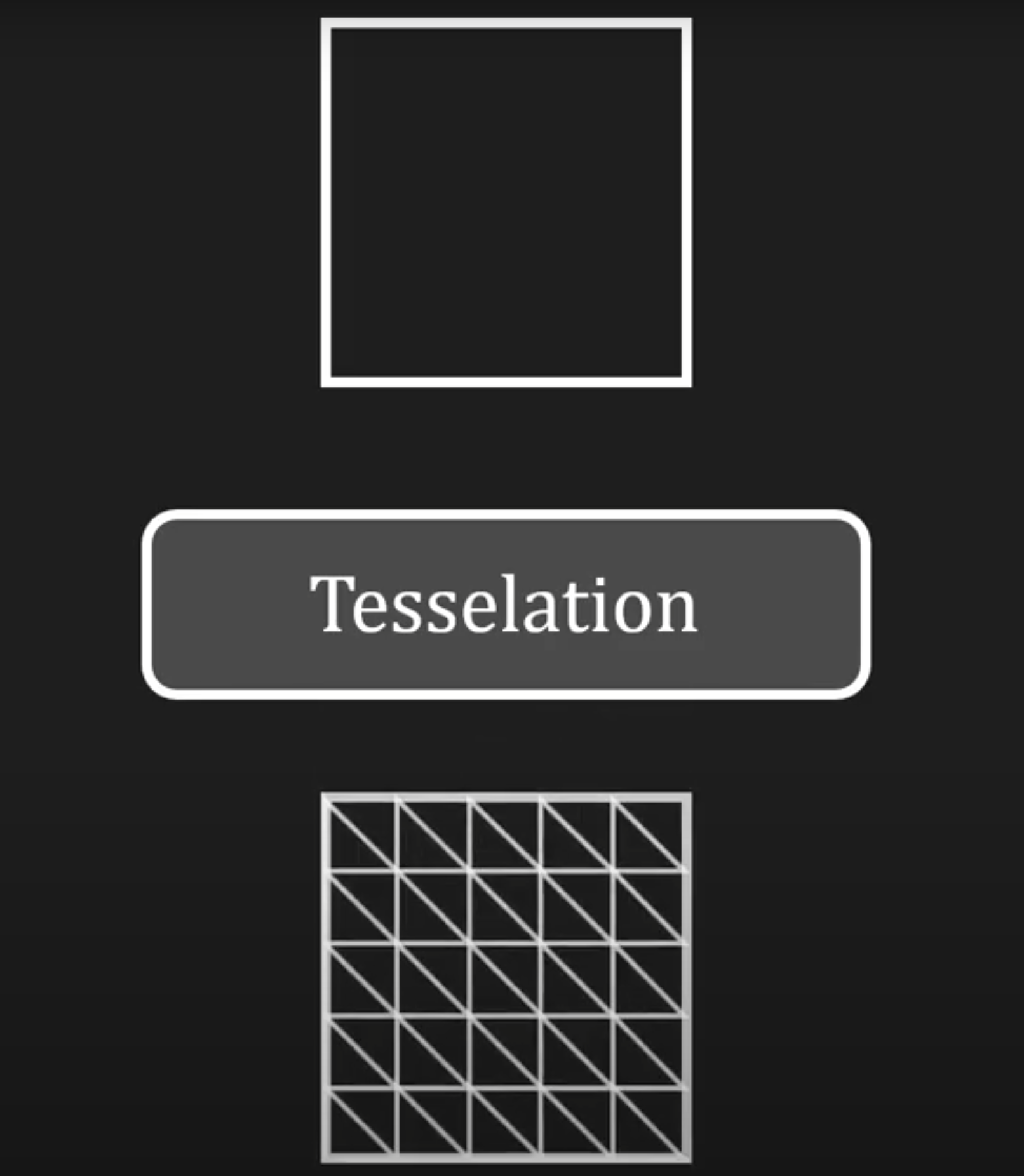
6.Geometry Shader stage
The Geometry Shader (GS) stage processes entire primitives: triangles, lines, and points, along with their adjacent vertices. It supports geometry amplification and de-amplification. It is useful for algorithms including Point Sprite Expansion, Dynamic Particle Systems, Fur/Fin Generation, Shadow Volume Generation, Single Pass Render-to-Cubemap, Per-Primitive Material Swapping, and Per-Primitive Material Setup - including generation of barycentric coordinates as primitive data so that a pixel shader can perform custom attribute interpolation.
-
Input
Unlike vertex shaders, which operate on a single vertex, the geometry shader's inputs are the vertices for a full primitive (three vertices for triangles, two vertices for lines, or single vertex for point). -
Output
The Geometry Shader (GS) stage is capable of outputting multiple vertices forming a single selected topology. Available geometry shader output topologies are tristrip, linestrip, and pointlist. The number of primitives emitted can vary freely within any invocation of the geometry shader, though the maximum number of vertices that could be emitted must be declared statically. Strip lengths emitted from a geometry shader invocation can be arbitrary, and new strips can be created via the RestartStrip HLSL function.

7.Stream Output stage 用来读回做更多骚操作
The Stream Output (SO) stage continuously outputs (or streams) vertex data from the previous active stage to one or more buffers in memory. Data streamed out to memory can be recirculated back into the pipeline as input data, or read-back from the CPU.
-
Input
Vertex data from a previous pipeline stage. -
Output
The Stream Output (SO) stage continuously outputs (or streams) vertex data from the previous active stage, such as the Geometry Shader (GS) stage, to one or more buffers in memory. If the Geometry Shader (GS) stage is inactive, and the Stream Output (SO) stage is active, it continuously outputs vertex data from the Domain Shader (DS) stage to buffers in memory (or if the DS is also inactive, from the Vertex Shader (VS) stage).
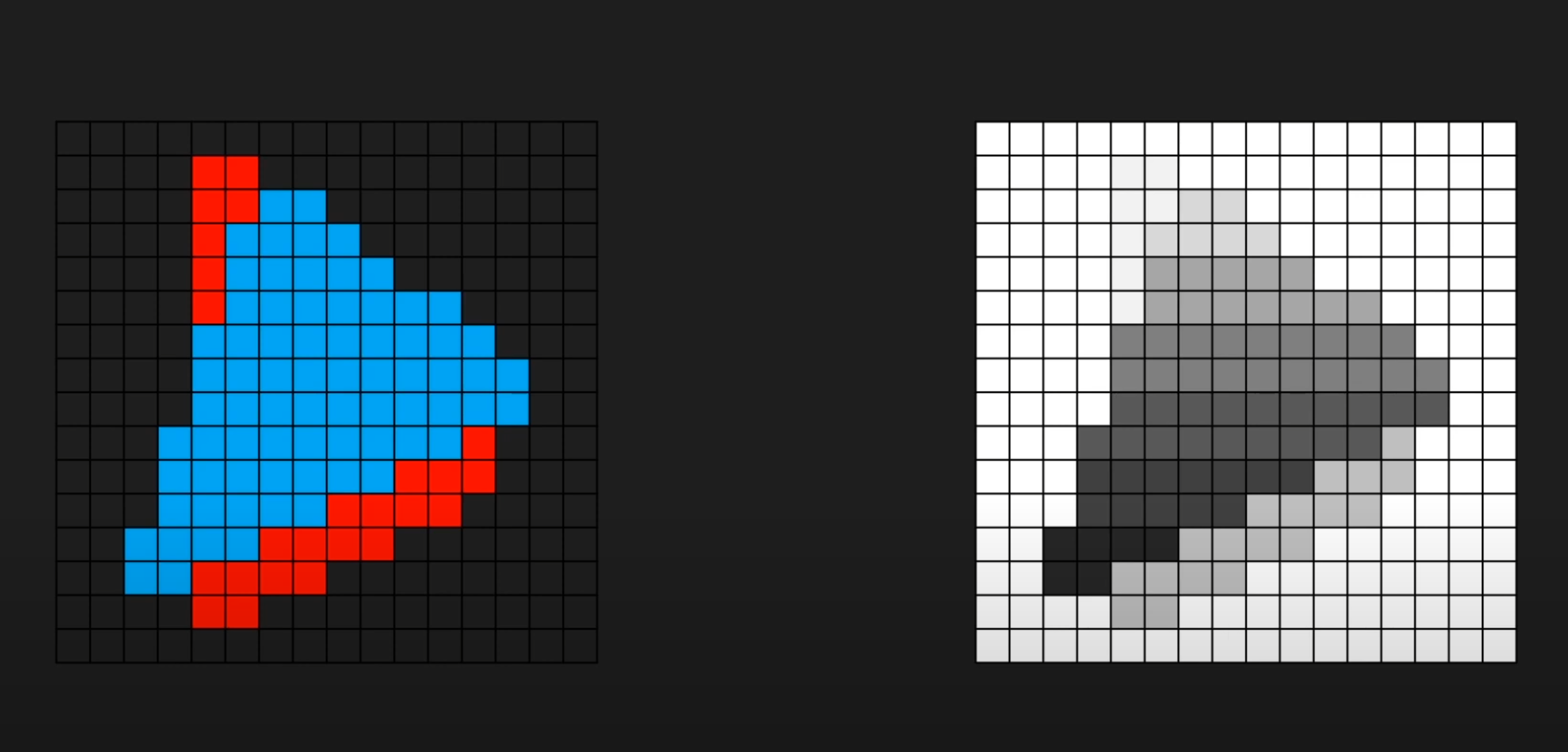
8.Rasterizer stage 开始把你们变成像素
The Rasterizer (RS) stage clips primitives that aren't in view, prepares primitives for the Pixel Shader (PS) stage, and determines how to invoke pixel shaders. Converts vector information (composed of shapes or primitives) into a raster image (composed of pixels) for the purpose of displaying real-time 3D graphics.
-
Input
Vertices (x,y,z,w) coming into the Rasterizer stage are assumed to be in homogeneous clip-space. In this coordinate space the X axis points right, Y points up and Z points away from camera. -
Output
The actual pixels that need to be rendered. Includes some vertex attributes for use in interpolation by the Pixel Shader.
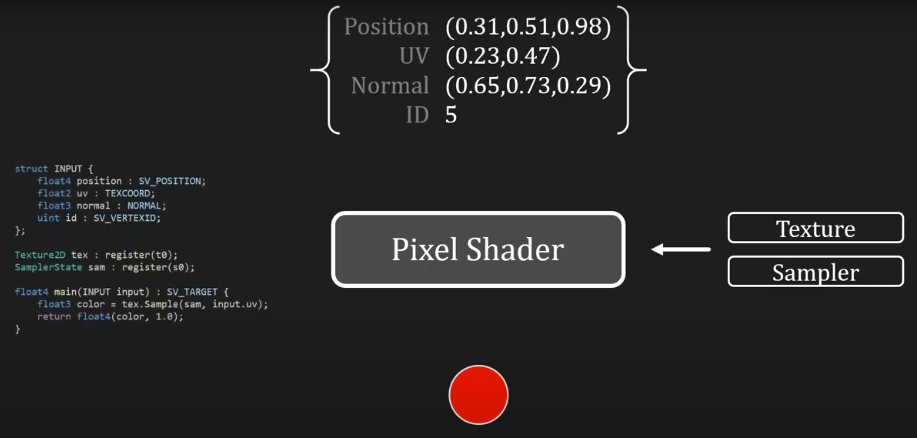
9.Pixel Shader stage
The Pixel Shader (PS) stage receives interpolated data for a primitive and generates per-pixel data such as color.
-
Input
When the pipeline is configured without a geometry shader, a pixel shader is limited to 16, 32-bit, 4-component inputs. Otherwise, a pixel shader can take up to 32, 32-bit, 4-component inputs. Pixel shader input data includes vertex attributes (that can be interpolated with or without perspective correction) or can be treated as per-primitive constants. Pixel shader inputs are interpolated from the vertex attributes of the primitive being rasterized, based on the interpolation mode declared. If a primitive gets clipped before rasterization, the interpolation mode is honored during the clipping process as well. -
Output
A pixel shader can output up to 8, 32-bit, 4-component colors, or no color if the pixel is discarded. Pixel shader output register components must be declared before they can be used; each register is allowed a distinct output-write mask.
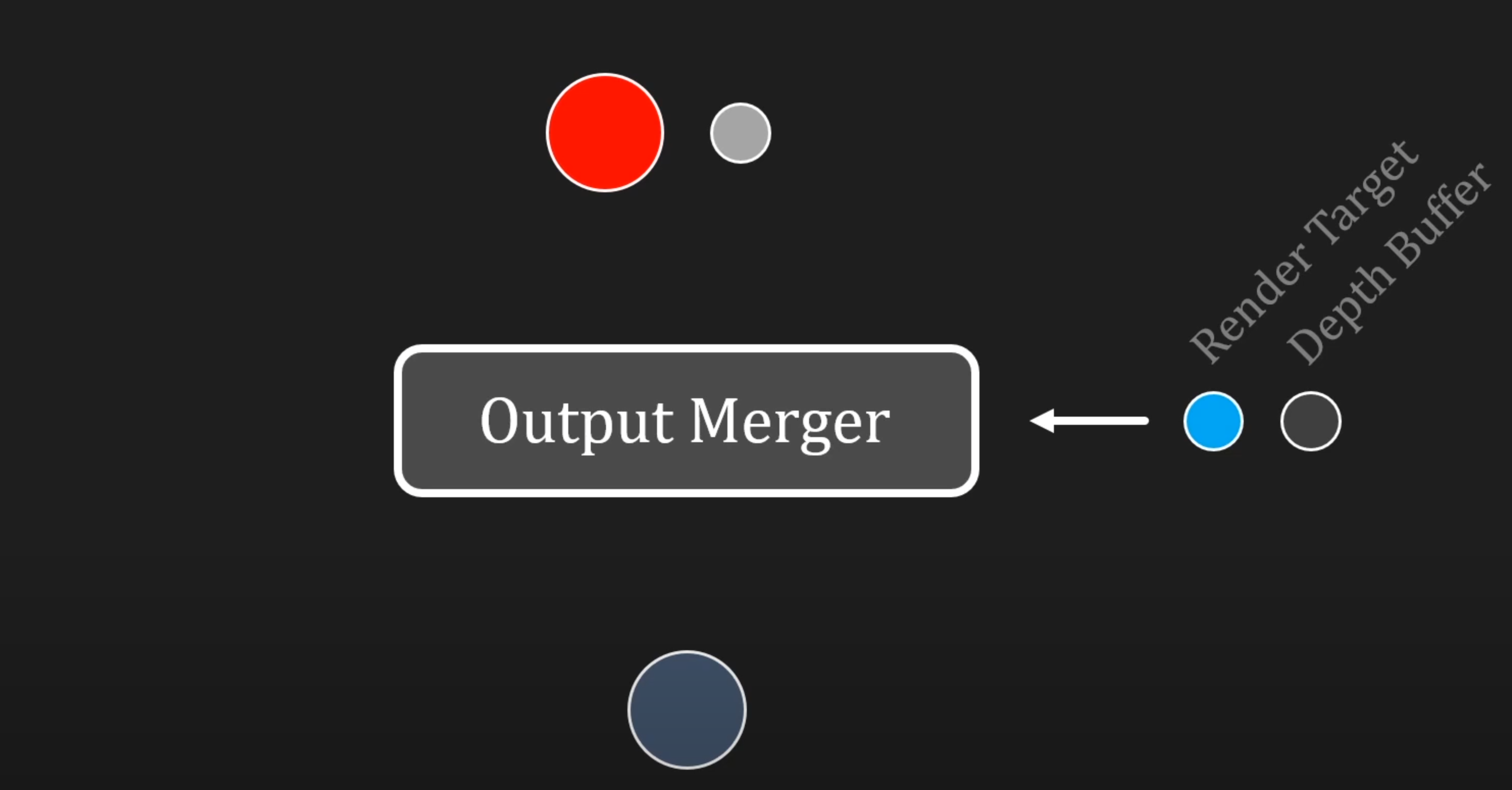
10.Output Merger stage alpha混合, stencil测试....etc
The Output Merger (OM) stage combines various types of output data (pixel shader values, depth and stencil information) with the contents of the render target and depth/stencil buffers to generate the final pipeline result.
-
Input
Output Merger inputs are the Pipeline state, the pixel data generated by the pixel shaders, the contents of the render targets and the contents of the depth/stencil buffers. -
Output
The final rendered pixel color.