MSP430-GPIO与中断相关库函数及例程
0、宏定义
端口
#define GPIO_PORT_P1                                                          1
#define GPIO_PORT_P2                                                          2
#define GPIO_PORT_P3                                                          3
#define GPIO_PORT_P4                                                          4
#define GPIO_PORT_P5                                                          5
#define GPIO_PORT_P6                                                          6
#define GPIO_PORT_P7                                                          7
#define GPIO_PORT_P8                                                          8
#define GPIO_PORT_P9                                                          9
#define GPIO_PORT_P10                                                        10
#define GPIO_PORT_P11                                                        11
#define GPIO_PORT_PA                                                          1
#define GPIO_PORT_PB                                                          3
#define GPIO_PORT_PC                                                          5
#define GPIO_PORT_PD                                                          7
#define GPIO_PORT_PE                                                          9
#define GPIO_PORT_PF                                                         11
#define GPIO_PORT_PJ                                                         13
引脚
#define GPIO_PIN0                                                      (0x0001)
#define GPIO_PIN1                                                      (0x0002)
#define GPIO_PIN2                                                      (0x0004)
#define GPIO_PIN3                                                      (0x0008)
#define GPIO_PIN4                                                      (0x0010)
#define GPIO_PIN5                                                      (0x0020)
#define GPIO_PIN6                                                      (0x0040)
#define GPIO_PIN7                                                      (0x0080)
#define GPIO_PIN8                                                      (0x0100)
#define GPIO_PIN9                                                      (0x0200)
#define GPIO_PIN10                                                     (0x0400)
#define GPIO_PIN11                                                     (0x0800)
#define GPIO_PIN12                                                     (0x1000)
#define GPIO_PIN13                                                     (0x2000)
#define GPIO_PIN14                                                     (0x4000)
#define GPIO_PIN15                                                     (0x8000)
#define GPIO_PIN_ALL8                                                    (0xFF)
#define GPIO_PIN_ALL16                                                 (0xFFFF)
复用功能
#define GPIO_PRIMARY_MODULE_FUNCTION                                     (0x01)
#define GPIO_SECONDARY_MODULE_FUNCTION                                   (0x02)
#define GPIO_TERNARY_MODULE_FUNCTION                                     (0x03)
1、API函数
-
配置为输出端口
void GPIO_setAsOutputPin(uint8_t selectedPort, uint16_t selectedPins) -
配置为输入端口
void GPIO_setAsInputPin(uint8_t selectedPort, uint16_t selectedPins) -
配置为复用功能输出
void GPIO_setAsPeripheralModuleFunctionOutputPin(uint8_t selectedPort, uint16_t selectedPins, uint8_t mode) -
配置为复用功能输入
void GPIO_setAsPeripheralModuleFunctionInputPin(uint8_t selectedPort, uint16_t selectedPins, uint8_t mode) -
输出高电平
void GPIO_setOutputHighOnPin(uint8_t selectedPort, uint16_t selectedPins) -
输出低电平
void GPIO_setOutputLowOnPin(uint8_t selectedPort, uint16_t selectedPins) -
翻转电平输出
void GPIO_toggleOutputOnPin(uint8_t selectedPort, uint16_t selectedPins) -
配置为下拉输入
void GPIO_setAsInputPinWithPullDownResistor(uint8_t selectedPort, uint16_t selectedPins) -
配置为上拉输入
void GPIO_setAsInputPinWithPullUpResistor(uint8_t selectedPort, uint16_t selectedPins) -
读取输入电平
uint8_t GPIO_getInputPinValue(uint8_t selectedPort, uint16_t selectedPins)返回
#define GPIO_INPUT_PIN_HIGH (0x01) #define GPIO_INPUT_PIN_LOW (0x00) -
使能中断
void GPIO_enableInterrupt(uint8_t selectedPort, uint16_t selectedPins) -
禁用中断
void GPIO_disableInterrupt(uint8_t selectedPort, uint16_t selectedPins) -
获取中断状态
uint16_t GPIO_getInterruptStatus(uint8_t selectedPort, uint16_t selectedPins) -
清除中断标志
void GPIO_clearInterrupt(uint8_t selectedPort, uint16_t selectedPins) -
选取中断沿
void GPIO_selectInterruptEdge(uint8_t selectedPort, uint16_t selectedPins, uint8_t edgeSelect)edgeSelect可选参数:GPIO_HIGH_TO_LOW_TRANSITION、GPIO_LOW_TO_HIGH_TRANSITION -
配置驱动能力
void GPIO_setDriveStrength(uint8_t selectedPort, uint16_t selectedPins, uint8_t driveStrength)·driveStrength·可选参数:
GPIO_REDUCED_OUTPUT_DRIVE_STRENGTH、GPIO_FULL_OUTPUT_DRIVE_STRENGTH
2、例程
说明
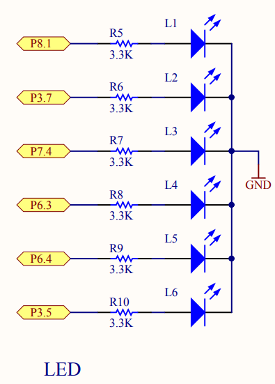
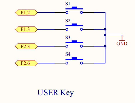
程序示例基于MSP430F5529 LaucnPad及拓展板套件,通过外部中断实现按键控制LED灯状态翻转,分别由S1,S2,S3按键控制L1,L2,L3的亮灭,每按下一次按键LED灯的状态翻转一次。硬件原理图如下:
源码
#include "driverlib.h"


// 消抖延时
void delay(int cnt)
{
    while(cnt)
        cnt--;
}

int main(void)
{

    WDT_A_hold(WDT_A_BASE);

    // 配置按键为上拉输入
    GPIO_setAsInputPinWithPullUpResistor(GPIO_PORT_P1, GPIO_PIN2 | GPIO_PIN3);  // S1 | S2
    GPIO_setAsInputPinWithPullUpResistor(GPIO_PORT_P2, GPIO_PIN3);  // S3
    // 使能中断
    _enable_interrupts();
    GPIO_enableInterrupt(GPIO_PORT_P1, GPIO_PIN2 | GPIO_PIN3);
    GPIO_enableInterrupt(GPIO_PORT_P2, GPIO_PIN3);
    // 选取为下降沿
    GPIO_selectInterruptEdge(GPIO_PORT_P1, GPIO_PIN2 | GPIO_PIN3, GPIO_HIGH_TO_LOW_TRANSITION);
    GPIO_selectInterruptEdge(GPIO_PORT_P2, GPIO_PIN3, GPIO_HIGH_TO_LOW_TRANSITION);
    // 清除中断标志
    GPIO_clearInterrupt(GPIO_PORT_P1, GPIO_PIN2 | GPIO_PIN3);
    GPIO_clearInterrupt(GPIO_PORT_P2, GPIO_PIN3);
    // LED配置为输出端口,默认输出高电平
    GPIO_setAsOutputPin(GPIO_PORT_P8, GPIO_PIN1);   GPIO_setOutputHighOnPin(GPIO_PORT_P8, GPIO_PIN1);    // L1
    GPIO_setAsOutputPin(GPIO_PORT_P3, GPIO_PIN7);   GPIO_setOutputHighOnPin(GPIO_PORT_P3, GPIO_PIN7);    // L2
    GPIO_setAsOutputPin(GPIO_PORT_P7, GPIO_PIN4);   GPIO_setOutputHighOnPin(GPIO_PORT_P7, GPIO_PIN4);    // L3

    return (0);
}

// 编写中断函数
// P1
#pragma vector=PORT1_VECTOR
__interrupt
void Port_1(void)
{
    delay(50000);
    if(!( GPIO_getInputPinValue(GPIO_PORT_P1, GPIO_PIN2) &
          GPIO_getInputPinValue(GPIO_PORT_P1, GPIO_PIN3) ))
    {
        //获取中断标志
        if(GPIO_getInterruptStatus(GPIO_PORT_P1, GPIO_PIN2))    // S1
        {
            GPIO_toggleOutputOnPin(GPIO_PORT_P8, GPIO_PIN1);    // L1
        }
        else    // S2
        {
            GPIO_toggleOutputOnPin(GPIO_PORT_P3, GPIO_PIN7);    // L2
        }
    }
    //清除中断标志位
    GPIO_clearInterrupt(GPIO_PORT_P1, GPIO_PIN2 | GPIO_PIN3);
}
// P2
#pragma vector=PORT2_VECTOR
__interrupt
void Port_2(void)
{
    delay(50000);
    if(!GPIO_getInputPinValue(GPIO_PORT_P2, GPIO_PIN3))
        GPIO_toggleOutputOnPin(GPIO_PORT_P7, GPIO_PIN4);    // L3
    //清除中断标志位
    GPIO_clearInterrupt(GPIO_PORT_P2, GPIO_PIN3);
}

 浙公网安备 33010602011771号