Verilog 刷题笔记(03)
20.In this exercise, create one instance of module mod_a, then connect the module's three pins (in1, in2, and out) to your top-level module's three ports (wires a, b, and out). The module mod_a is provided for you — you must instantiate it. You may connect signals to the module by port name or port position. For extra practice, try both methods.
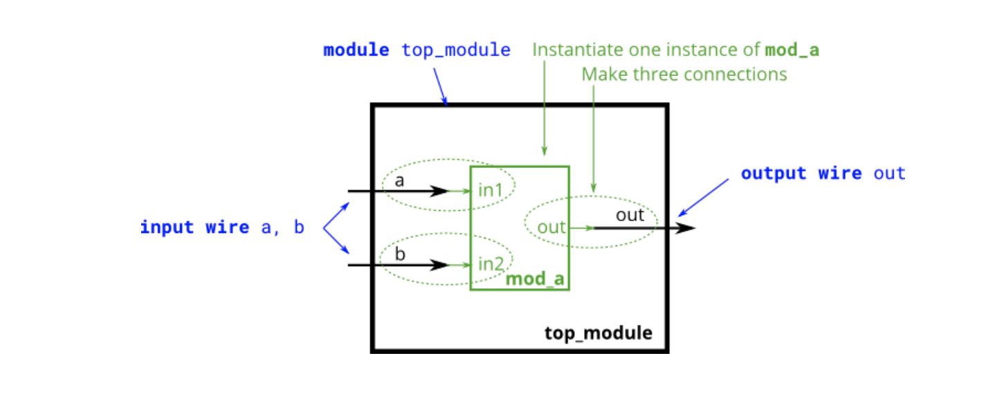
//创建一个名为 名为 "inst1"的实例"mod_a",并按名称连接端口
module top_module ( input a, input b, output out );

    mod_a inst1(
        .in1(a),    //端口in1 连接到 线a
        .in2(b),    //端口in2 连接到 线b
        .out(out)   //端口out 连接到 线out
    );
endmodule
/*
//创建一个名为 名为 "inst2"的实例"mod_a",并按名称连接端口, 并按位置连接端口:
mod_a inst2 ( a, b, out ); // 这三条线分别连接到端口in1、in2和out。
*/
21. You are given a module named mod_a that has 2 outputs and 4 inputs, in that order. You must connect the 6 ports by position to your top-level module's ports out1, out2, a, b, c, and d, in that order. You are given the following module:
module mod_a ( output, output, input, input, input, input );

module top_module (
    input a,
    input b,
    input c,
    input d,
    output out1,
    output out2
);
  //connecting ports by position
    mod_a inst1(
        out1,
        out2,
        a,
        b,
        c,
        d
    );

endmodule
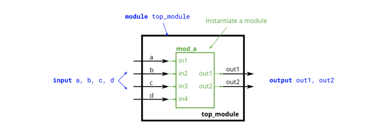
22. You are given a module named mod_a that has 2 outputs and 4 inputs, in some order. You must connect the 6 ports by name to your top-level module's ports:
Port in mod_a | Port in top_module |
|---|---|
output out1 |
out1 |
output out2 |
out2 |
input in1 |
a |
input in2 |
b |
input in3 |
c |
input in4 |
d |
You are given the following module:
module mod_a ( output out1, output out2, input in1, input in2, input in3, input in4);
module top_module (
    input a,
    input b,
    input c,
    input d,
    output out1,
    output out2
);

// connecting ports by name
    mod_a inst1(
        .out1(out1),
        .out2(out2),
        .in1(a),
        .in2(b),
        .in3(c),
        .in4(d)
    );
endmodule
23.You are given a module my_dff with two inputs and one output (that implements a D flip-flop). Instantiate three of them, then chain them together to make a shift register of length 3. The clk port needs to be connected to all instances. The module provided to you is:
module my_dff ( input clk, input d, output q );

module top_module ( input clk, input d, output q );

    //创建my_dff的三个实例,有三个不同的实例名称(d1、d2和d3)。
    //按位置连接端口。( 输入clk, 输入d, 输出q)

    wire a,b;
    my_dff d1 (clk, d, a );
    my_dff d2 (clk, a, b );
    my_dff d3 (clk, b, q );

endmodule
24. You are given a module my_dff8 with two inputs and one output (that implements a set of 8 D flip-flops). Instantiate three of them, then chain them together to make a 8-bit wide shift register of length 3. In addition, create a 4-to-1 multiplexer (not provided) that chooses what to output depending on sel[1:0]: The value at the input d, after the first, after the second, or after the third D flip-flop. (Essentially, sel selects how many cycles to delay the input, from zero to three clock cycles.)The module provided to you is:
module my_dff8 ( input clk, input [7:0] d, output [7:0] q );

module top_module (
    input clk,
    input [7:0] d,
    input [1:0] sel,
    output [7:0] q
);

    wire [7:0] o1,o2,o3;	//my_dff的三个输出
    //实例化三个my_dff8
    my_dff8 d1  (clk,  d, o1);
    my_dff8 d2  (clk, o1, o2);
    my_dff8 d3  (clk, o2, o3);

	// 这是制作4对1复用器的一种方法
    always @(*)		// 组合式总块
        case (sel)
            2'h0: q = d ;
            2'h1: q = o1;
            2'h2: q = o2;
            2'h3: q = o3;
        endcase

endmodule
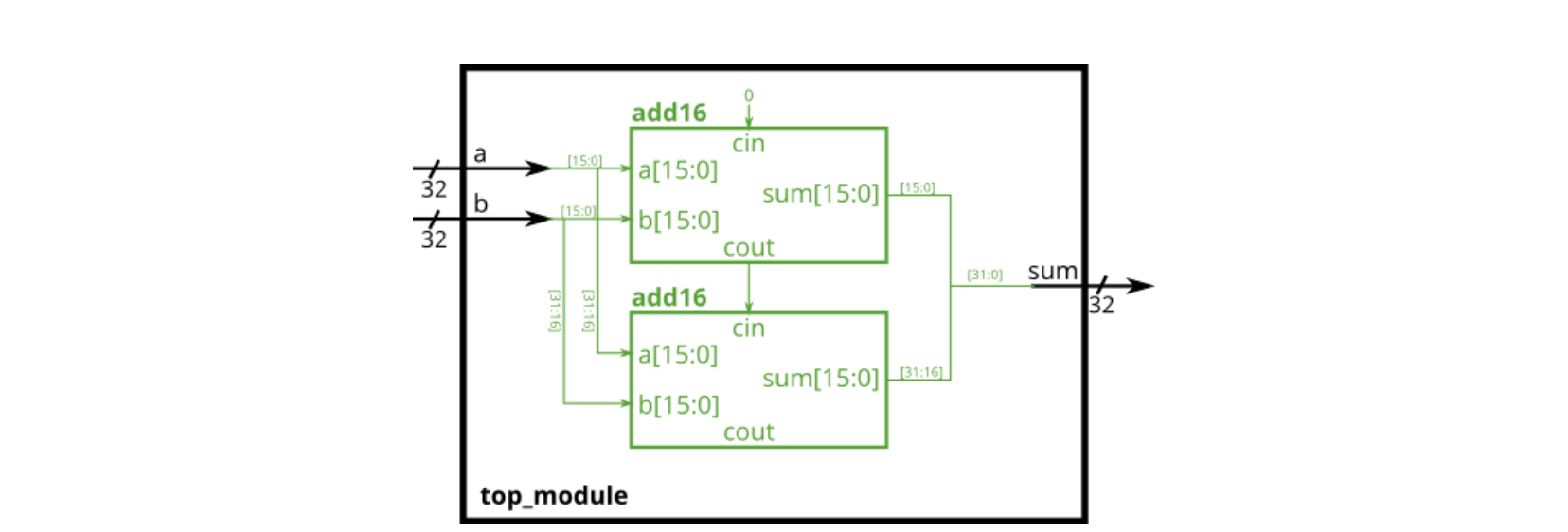
25.Connect the modules together as shown in the diagram below. The provided module add16 has the following declaration:
module add16 ( input[15:0] a, input[15:0] b, input cin, output[15:0] sum, output cout );
module top_module(
    input [31:0] a,
    input [31:0] b,
    output [31:0] sum
);
    wire cin1,cout1,cout2;
    wire [15:0] sum1,sum2;
    assign cin1=1'b0;

    //两个累加器分别从0~15,16~31,且注意输入/输出顺序!!!
    add16 inst1 (a[15:0],b[15:0],cin1,sum1,cout1);
    add16 inst2 (a[31:16],b[31:16],cout1,sum2,cout2);
    assign sum={sum2,sum1};
endmodule
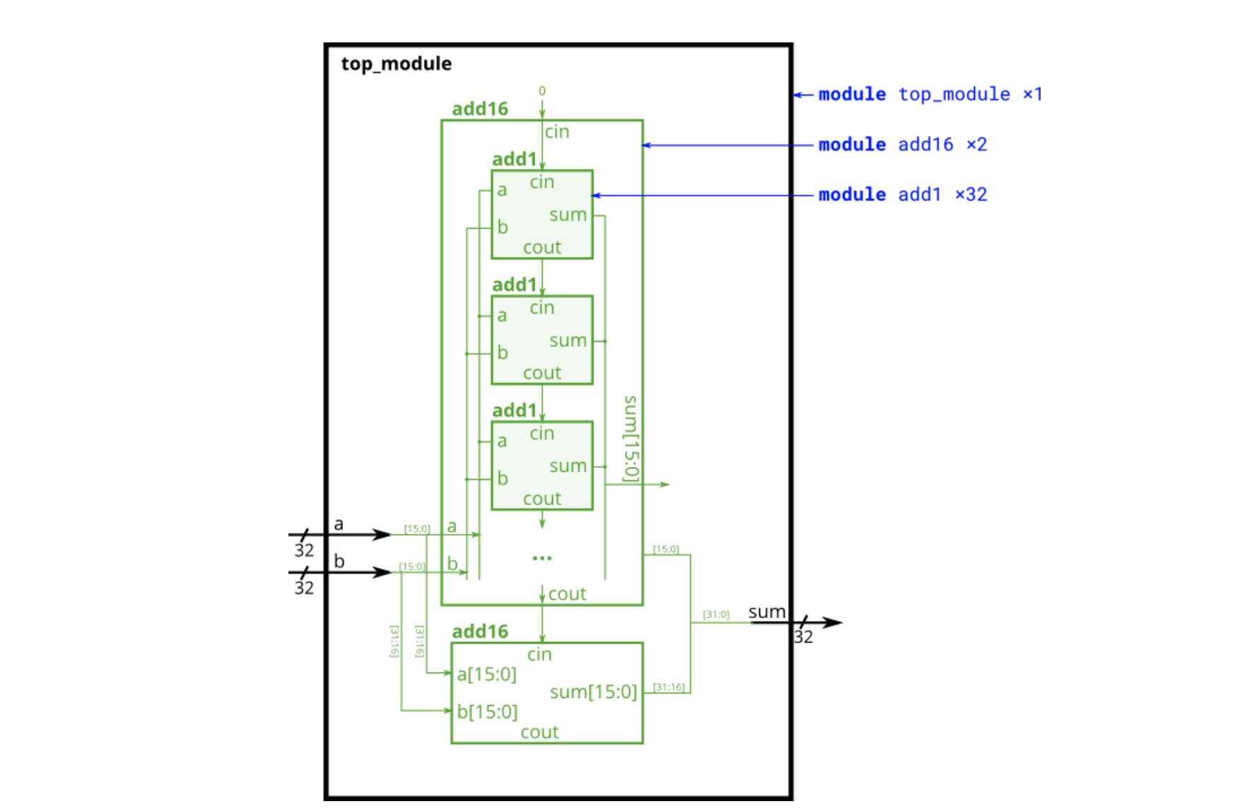
26.Connect the add16 modules together as shown in the diagram below. The provided module add16 has the following declaration:
module add16 ( input[15:0] a, input[15:0] b, input cin, output[15:0] sum, output cout );
Within each add16, 16 full adders (module add1, not provided) are instantiated to actually perform the addition. You must write the full adder module that has the following declaration:
module add1 ( input a, input b, input cin, output sum, output cout );
Recall that a full adder computes the sum and carry-out of a+b+cin.
In summary, there are three modules in this design:
top_module— Your top-level module that contains two of...add16, provided — A 16-bit adder module that is composed of 16 of...add1— A 1-bit full adder module
//纹波进位加法器
module top_module (
    input [31:0] a,
    input [31:0] b,
    output [31:0] sum
);//

    //第一个module和上一个题目一样,抄下来即可
    wire [15:0]sum1,sum2;
    wire out1,out2,in1;
    assign in1 = 1'b0;

    add16 inst1 (a[15:0],b[15:0],in1,sum1,out1);
    add16 inst2 (a[31:16],b[31:16],out1,sum2,out2);
    assign sum = {sum2,sum1};
endmodule

module add1 ( input a, input b, input cin, output sum, output cout );

// Full adder module here
    assign sum = a^b^cin;
    assign cout = (a|cin)&(b|cin)&(a|b);

endmodule
27. In this exercise, you are provided with the same module add16 as the previous exercise, which adds two 16-bit numbers with carry-in and produces a carry-out and 16-bit sum. You must instantiate three of these to build the carry-select adder, using your own 16-bit 2-to-1 multiplexer. Connect the modules together as shown in the diagram below. The provided module add16 has the following declaration:
module add16 ( input[15:0] a, input[15:0] b, input cin, output[15:0] sum, output cout );
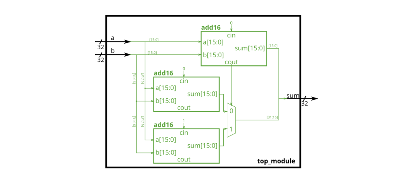
module top_module(
    input [31:0] a,
    input [31:0] b,
    output [31:0] sum
);

    //申明变量
    wire [15:0] sum1,sum2,sum3;
    wire cin1,cin2,cin3,cout1,cout2,cout3;
    //赋初值
    assign cin1 = 1'b0;
    assign cin2 = 1'b0;
    assign cin3 = 1'b1;
    //实例化
    add16 inst1 (a[15:0],b[15:0],cin1,sum1,cout1);
    add16 inst2 (a[31:16],b[31:16],cin2,sum2,cout2);
    add16 inst3 (a[31:16],b[31:16],cin3,sum3,cout3);

    always@(*)
        case (cout1)
            1'b0:sum = {sum2,sum1};
            1'b1:sum = {sum3,sum1};
        endcase

endmodule
28.An adder-subtractor can be built from an adder by optionally negating one of the inputs, which is equivalent to inverting the input then adding 1. The net result is a circuit that can do two operations: (a + b + 0) and (a + ~b + 1). Build the adder-subtractor below. You are provided with a 16-bit adder module, which you need to instantiate twice:
module add16 ( input[15:0] a, input[15:0] b, input cin, output[15:0] sum, output cout );

module top_module(
    input [31:0] a,
    input [31:0] b,
    input sub,
    output [31:0] sum
);

    //申明变量
    wire [15:0] sum1,sum2;
    wire [31:0] bin;
    wire cout1,cout2;

    //分配线和端口
    assign bin = {32{sub}}^b;	//bin = 32位的sub和b按位异或的输出;

    //实例化模块
    add16 inst1 (a[15:0],bin[15:0],sub,sum1,cout1);
    add16 inst2 (a[31:16],bin[31:16],cout1,sum2,cout2);

    //输出sum
    assign sum = {sum2,sum1};


endmodule


