Computer Networking: Transport layer
A transport-layer protocol provides for logical communication between application processes running on different hosts.
Transport-layer protocols are implemented in the end systems (not in network router).
On the sending side
[application layer]messages -encapsulate-> [transport layer]segments -encapsulate-> [network layer]datagrams
On the receiving side
[network layer]datagrams -extract-> [transport layer]segments -extract-> [application layer]messages
Network routers act only on the network-layer fields of the datagram, they do no examine the transport-layer fields of the datagram.
Relationship between transport layer and network layer
A transport-layer protocol provides logical communication between processes running on different hosts;
A network-layer protocol provides logical communication between hosts.
The services that a transport protocol can provide are often constrained by the service model of the underlying network-layer protocol; E.g. delay/bandwidth guarantees.
But a transport protocol can provide certain services when the underlying network protocol does not offer corresponding service. E.g. reliable data transfer.
Transport layer service model
The Internet’s transport protocols:
1) UDP (User Datagram Protocol); 2) TCP (Transmission Control Protocol).
IP (Internet protocol): The Internet’s network layer protocol, is a best-effort delivery, unreliable service.
Every host has an network-layer IP address.
Transport-layer multiplexing and demultiplexing: Extending IP’s host-to-host delivery service [provided by the network layer] to process-to-process delivery service [for application running on the hosts]. (The most fundamental)
UDP provides only two minimal transport-layer services – 1) process-to process data delivery; 2) error checking (i.e. integrity checking by including error-detection field in segments’ headers).
TCP offers several additional services: Reliable data transfer, congestion control.
Multiplexing and demultiplexing
Demultiplexing: The job of delivering the data in a transport-layer segment to the correct socket.
Multiplexing: The job of gathering data chunks at the source host from different sockets, encapsulating each data chunk with header information to create segments, and passing the segments to the network layer.
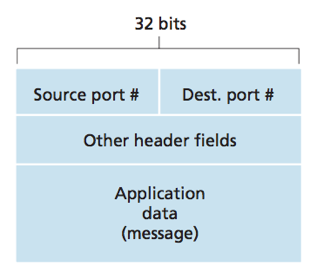
The source port number field and the destination port number field are special fields that indicate the socket to which the segment is to be delivered.
Each port number is a 16-bit number, ranging from 0 to 65535.
system port group: port numbers from 1 to 1023 (0 is reserved), reserved for use by well-known services. E.g. HTTP(80), FTP(21).
ephermeral port group: port number from 1024 to 65535, modern OSs select source ports randomly in this range.
Each socket in the host could be assigned a unique port number. When a segment arrives to the host, the transport layer examines the destination port number in the segment and directs it to the corresponding socket. The segment’s data then passes through the socket into the attached process. (basically how UDP does it).
Difference between UDP and TCP in multiplexing & demultiplexing
A UDP socket is identified by a two-tuple: (destination IP address, destination port number);
Two UDP segments with the same (destination IP address, destination port number) will be directed to the same destination process via the same destination socket.
In UDP socket, the source port number serves as part of a “return address”. (use to send segment back)
A TCP socket is identified by a four-tuple: (source IP address, source port number, destination IP address, destination port number).
Two TCP segments with the same (destination IP address, destination port number) but different (source IP address, source port number) will be directed to two different sockets. (Exception: TCP segments carrying the original connection-establishment request.)
TCP demultiplexing
1) The TCP server has a welcoming socket waits for connection-establishment requests from TCP clients on port number 6789. (notice: can use a different port number, but must make sure the same number is used on both sides.)
2) The TCP client sends a connection-request segment with destination port number 6789 through a TCP socket.
3) The server receives the connection-request segment through the welcoming socket, creates a new connection socket that is identified by the (source IP address, source port number, destination IP address, destination port number) in the connection request segment.
4) All subsequent arriving segments whose (source IP address, source port number, destination IP address, destination port number) match will be demultiplexed to that connection socket.
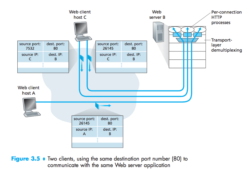
Web Server and TCP
When clients (browsers) send segments to the server, all segments (both the initial connection-establishment segments and the segments carrying HTTP request messages) will have destination port 80.
There is not always a one-to-one correspondence between connection sockets and processes.
a) In Fig3.5,the Web server spawns a new process for each connection, each process has its own connection socket;
b) Today’s high-performing Web servers often use only one process, and create a new thread with a new connection socket for each new client connection.
If the client and server use persistent HTTP, then throughout the duration of the persistent connection the client and the server exchange HTTP messages via the same server socket;
If the client and server use non-persistent HTTP, then a new TCP connection is created and later closed for every request/response. (So does a new socket.)
Connectionless Transport: UDP
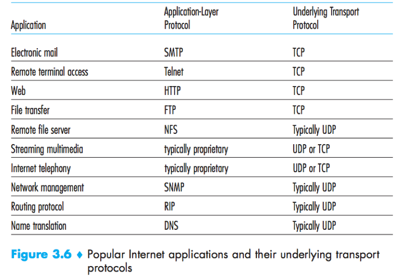
UDP Segment Structure
The header has 4 fields (source port number, destination port number, length, checksum), each consisting of 2 bytes. The data field is occupied by the application data.
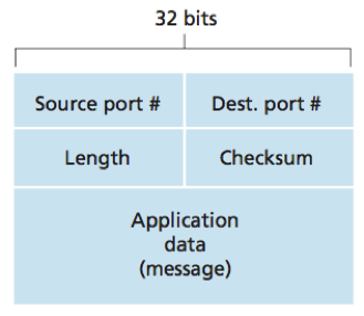
UDP checksum
The UDP checksum is used to determine whether bits within the UDP segment have been altered as it moved from source to destination.
UDP at the sender side performs the 1s complement of the sum of all the 16-bit words in the segment with any overflow encountered during the sum being wrapped around, then the result is put in the checksum field of the UDP segment.
UDP at the receiver adds all 16-bit words (including the checksum) if no errors are introduced, the sum will be 1111111111111111 (16 1s). If one of the bits is a 0, then errors have been introduced into the packet.
Although UDP provides error checking, it does not do anything to recover from an error.
e.g.
Given following three 16-bit words:
0110011001100000
0101010101010101
1000111100001100
sum (overflow wrapped around):
0100101011000010
checksum is the 1s complement (反码) of the sum: 1011010100111101
At the receiver, the sum of all three 16-bit words and the checksum equals 1111111111111111 if no errors are introduced.
Principle of reliable data transfer

The layer below the reliable data transfer protocol may be unreliable.
e.g. TCP is a reliable data transfer protocol that is implemented on top of an unreliable IP network layer.
The finite-state machine (FSM) definitions for rdt sender and receiver
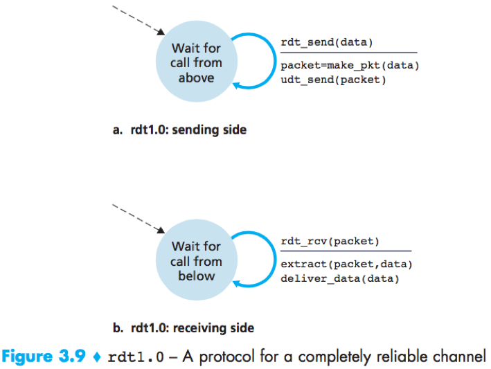
Rdt1.0
rdt2.0
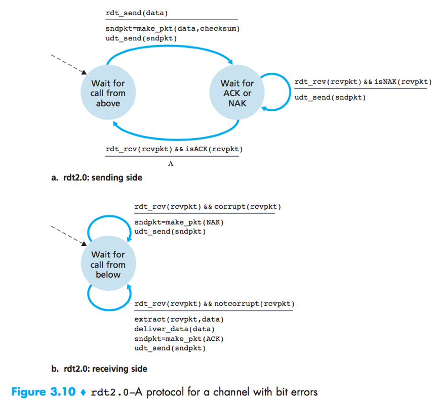
ARQ (Automatic Repeat reQuest) protocols: Reliable data transfer protocols based on error detection, receiver feedback (ACK/NAK) and retransmission.
rdt2.0 is a stop-and-wait protocol, because the sender will not send a new piece of data until it is sure that the receiver has correctly received the current packet.
rdt2.1
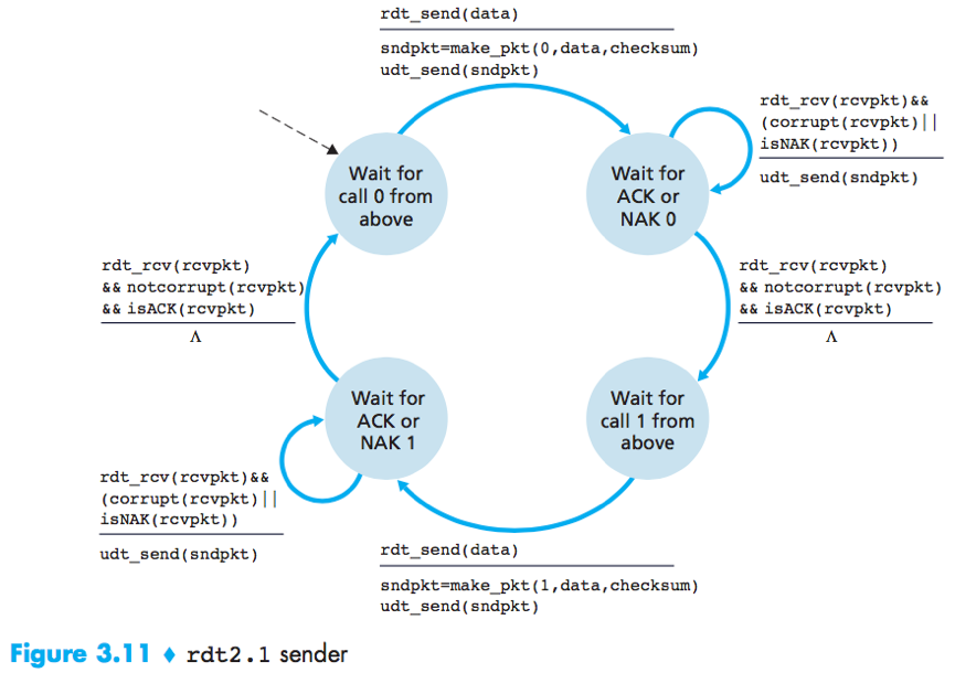
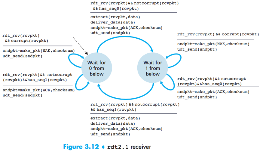
To handle corrupted ACKs or NAKs, the sender can simply resend the current data when it receives a garbled ACK or NAK packet.
Duplicate packets problem: The receiver cannot know a priori whether an arriving packet contains new data or is a retransmission.
Solution: Add a new field to the data packet, have the sender number its data packets by putting a sequence number into this field. The receiver then need only check this sequence number to determine whether or not the received packet is a retransmission.
rdt2.2
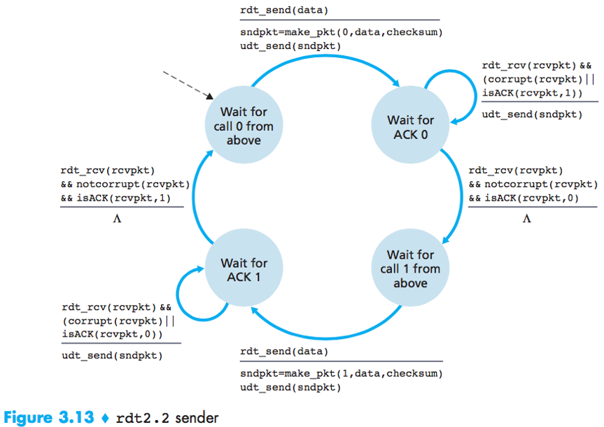
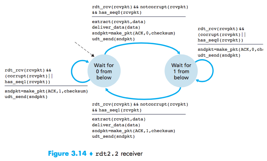
rdt2.2 is an NAK-free reliable data transfer protocol for a channel with bit errors, it sends an ACK for the last correctly received packet. A sender that receives 2 ACKs for the same packet (i.e. duplicate ACKs) knows that the receiver did not correctly receive the packet following the packet that is being ACKed twice.
rdt3.0 a.k.a. alternating-bit protocol.
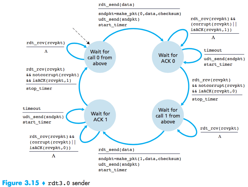
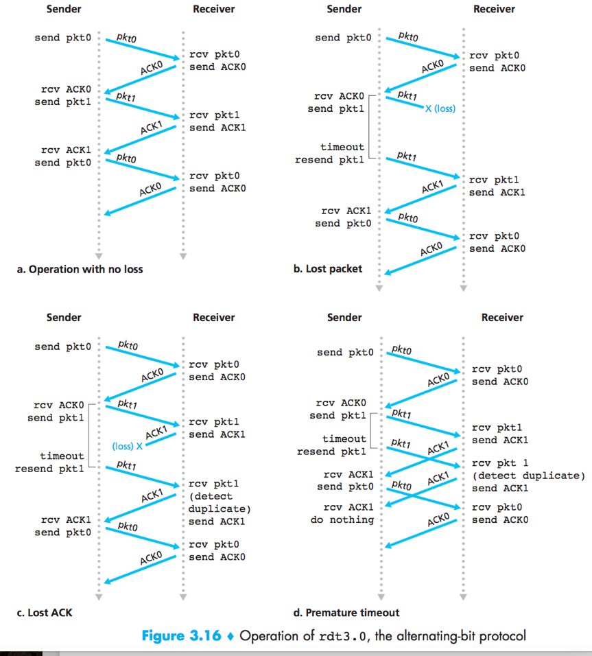
rdt3.0 is a protocol that reliably transfers data over a channel that can corrupt or lose packets.
The ender judiciously chooses a time value such that packet loss is likely, although not guaranteed, to have happened. If an ACK is not received within this time, the packet is retransmitted.
(The possible duplicate data packets problem will be handled by sequence numbers in rdt2.2.)
Pipelined reliable data transfer protocols
The performance of A stop-and-wait protocol is poor.
Solution: pipelining – Allow the sender to send multiple packets without waiting for acknowledgements.
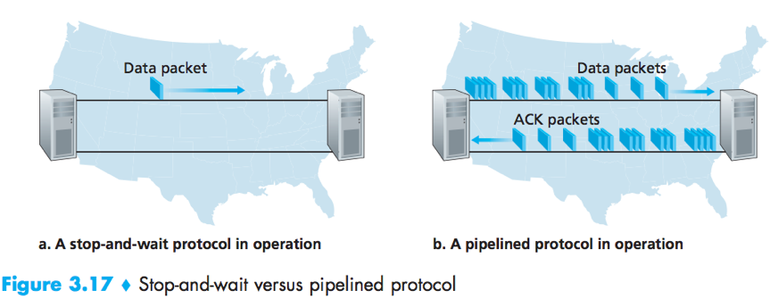
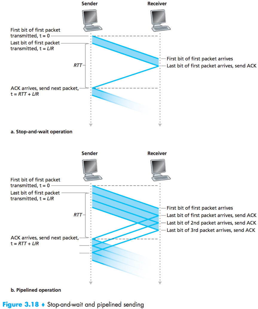
Two basic approaches toward pipelined error recovery: Go-Back-N and selective repeatprotocols.
Go Back-N (GBN) protocol: The sender is allowed to transmit multiple packets without waiting for an acknowledgment, but is constrained to have no more than some maximum allowable number N, of unacknowledged packets in the pipeline.
GBN protocol is a sliding-window protocol with window size = N.

base: the sequence number of the oldest unacknowledged packet;
nextseqnum: the sequence number of the next packet to be sent;
Sequence numbers >= base+N cannot be used until the packet with sequence number base has been acknowledge.
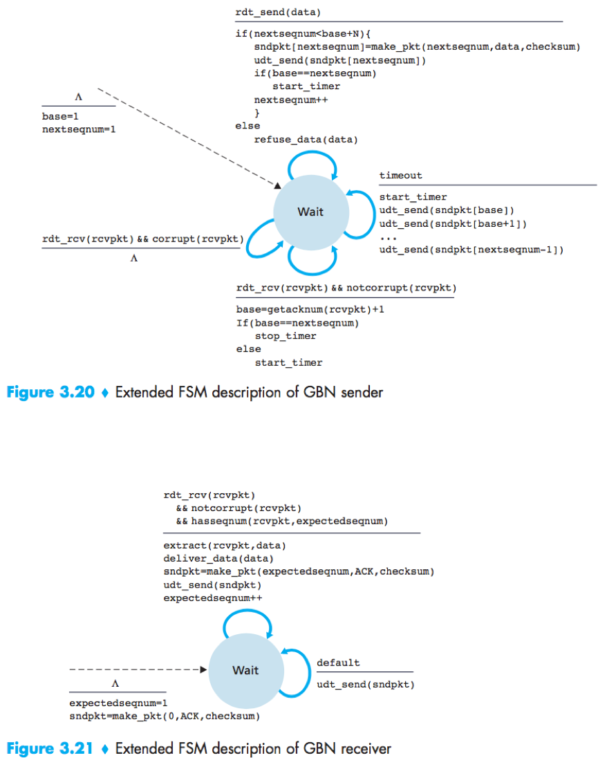
Cumulative acknowledgment: In GBN protocol, an acknowledgement for a packet with sequence number n indicates that all packets with a sequence number up to and including n have been correctly received at the receiver.
In GBN protocol, the receiver discards out-of-order packets, thus the sender must maintain the upper and lower bounds of its window and the position of nextseqnum within this window, and the receiver need maintain only the sequence number of the next in-order packet.
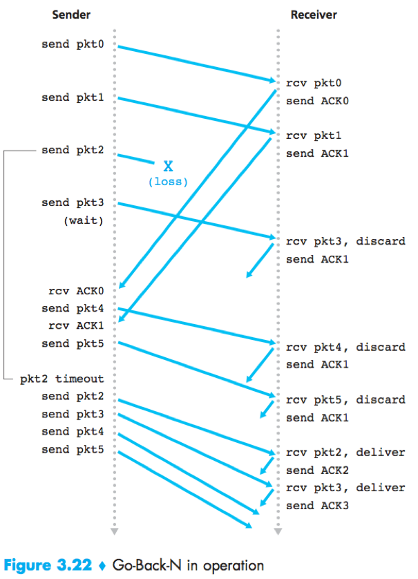
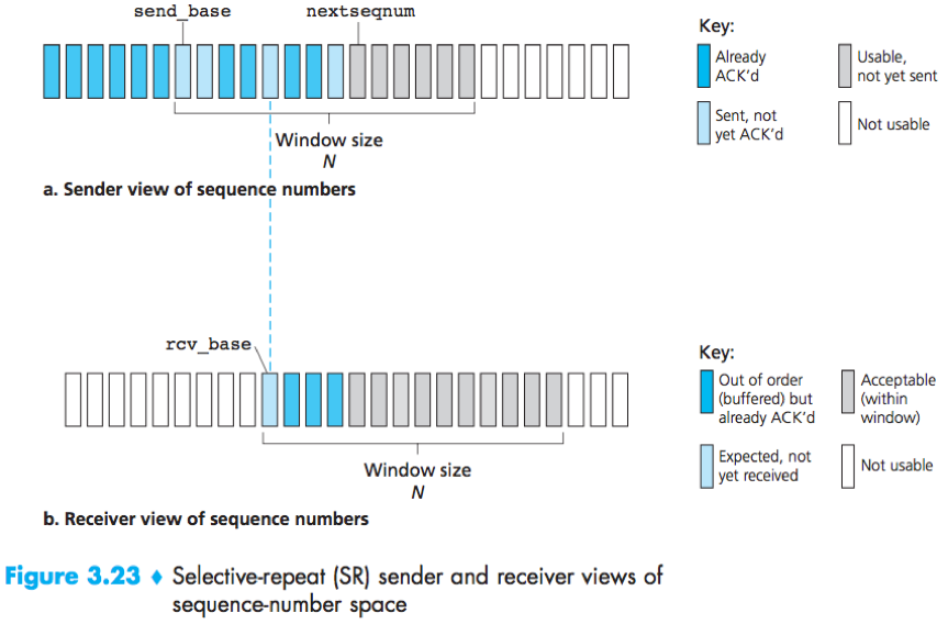
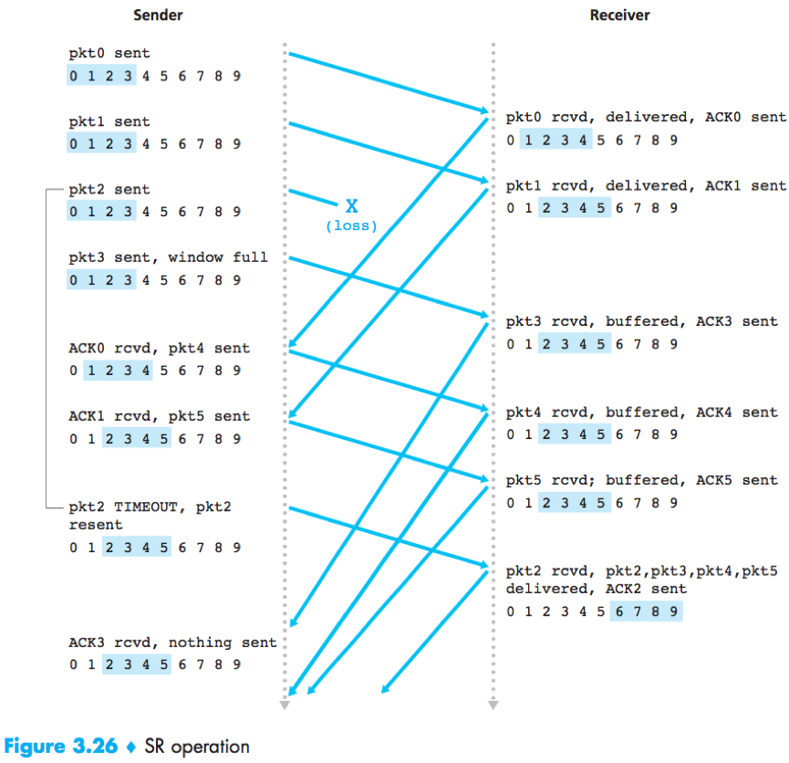
Selective Repeat (SR): The receiver individually acknowledges correctly received packets, and the sender retransmit only those packets that it suspects were received in error (lost/corrupted) to avoid unnecessary retransmissions.
Unlike GBN, the sender will have already received ACKs for some of the packets in the window.
The SR receiver will acknowledge a correctly received packet whether or not it is in order, out-of-order packets are buffered until any missing packets are received.
The sender and receiver windows will not always coincide, so the receiver should reacknowledges already received packets with certain sequence numbers below the current window base (i.e. in [rcv_base-N, rcv_base-1]).
The window size must be less than or equal to half the size of the sequence number space for SR protocols.
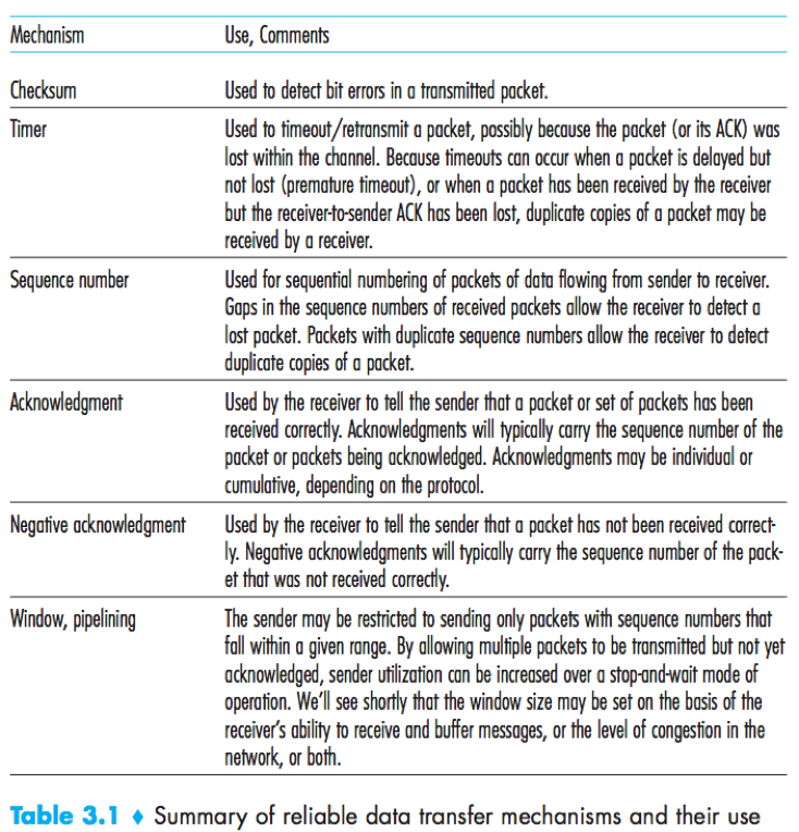
Reliable data transfer can be provided by link-, network-, transport-, or application-layer protocols, any of these 4 layers can implement acknowledgment, timers, retransmissions and sequence numbers, and provide reliable data transfer to the layer above.
Connection-Oriented Transport: TCP
The TCP connection
TCP is connection-oriented because before one application process can begin to send data to another, the two processes must first “handshake” with each other.
The TCP protocol runs only in the end systems, the intermediate network elements (e.g. routers, switches and repeaters) do not maintain TCP connection state.
A TCP connection provides a full duplex service.
A TCP connection is point-to-point (no multicasting.).
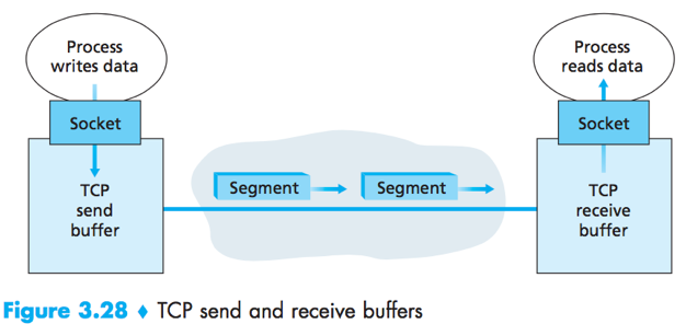
TCP send buffer and receive buffer are set aside during the initial three-way handshake. Each side of the connection has its own send buffer and its own receive buffer.
From time to time, TCP will grab chunks of data from the send buffer, the maximum amount of data that can be grabbed and placed in a segment is limited by the MSS.
Maximum segment size (MSS): The maximum amount of application-layer data in the segment.
Maximum transmission unit (MTU): The length of the largest link-layer frame that can be sent by the local sending host.
TCP Segment Structure
When sending a large file, TCP breaks it into chunks of size MSS (except for the last chunk).
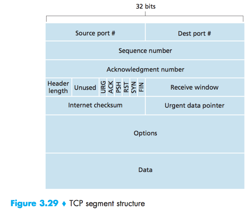
Source and destination port numbers: used for multiplexing/demultiplexing.
Sequence number and Acknowledgement number are used in implementing a reliable data transfer service.
Sequence number (32 bits): used to identify a TCP segment, ensuring that parts of a data stream are not missing.
Acknowledgment number (32 bits): to be expected in the next packet from the other device taking part in the communication.
Header length: specifies the length of the TCP header in 32-bit words.
The TCP header is typically 20 bytes, but can be of variable length due to the TCP option field (typically is empty).
Flags (6 bits) are for identifying the type of the TCP packet.
URG bit indicates that there is data in the segment that the sending-side upper-layer entity has marked as “urgent”;
ACK bit: indicates that the value carried in the acknowledgement field is valid;
PSH bit: indicates that the receiver should pass the data to the upper layer immediately;
The RST, SYN and FIN bits are used for connection setup and teardown;
Receive window field (16 bits): used for flow control, to indicate the number of bytes that a receiver is willing to accept.
Checksum field
Urgent data pointer: If URG flag is set, this field indicates the location of the last byte of the urgent data -- gives instruction for where CPU should begin reading the data.
Options field: optional and variable-length, used when a sender and receiver negotiate the MSS or as a window scaling factor for use in high-speed networks.
Sequence numbers and acknowledgment numbers

(The initial sequence number doesn’t have to be 0, both sides of a TCP connection randomly choose an initial sequence number.)
The sequence number for a segment is the byte-stream number of the first byte in the segment.
e.g.
File = 500000 bytes, MSS = 1000 bytes. ⇒
Sequence number for 1st segment = 0;
Sequence number for 2nd segment = 1000;
…
The acknowledgement number that Host A puts in its segment is the sequence number of the next byte Host A is expecting from Host B.
Cumulative acknowledgments: TCP only acknowledges bytes up to the first missing byte in the stream.
e.g.
Host A has received bytes numbered 0 through 535 from B, and is about to send a segment to Host B. ⇒
A puts 536 in the acknowledgment number field of the segment it sends to B.
e.g.
Host A has received one segment from Host B containing bytes 0 through 535, and another segment containing bytes 900 through 1000. (not received 536 through 899) ⇒
A still puts 536 in the acknowledgement number field of the segment it sends to B.
e.g.
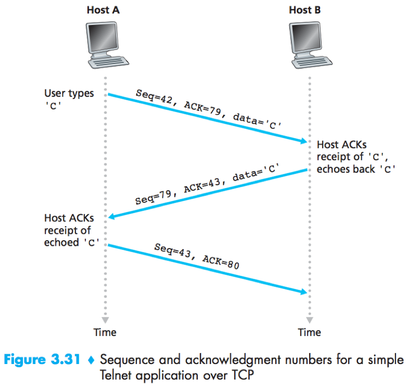
What does a host do when it receives out-of-order segments in a TCP connection?
The TCP RFC leave the decision up to the people programming a TCP implementation.
Choice A: The receiver discard out-of-order segments;
Choice B: The receiver keeps the out-of-order bytes and waits for the missing bytes to fill in the gaps. (taken in practice.)
Round-trip time estimation and timeout
1) Estimating the RTT
SampleRTT: The amount of time between when a segment is sent and when an acknowledgement for the segment is received.
EstimatedRTT: Some sort of average of the sampleRTT values.
EstimatedRTT = (1-α)·EstimatedRTT+ α·SampleRTT
(Recommended value of α = 0.125)
DevRTT: An estimate of how much SampleRTT typically deviates from EstimatedRTT, will be small if the SampleRTT values have little fluctuation.
DevRTT = (1-β)·DevRTT+ β·|SampleRTT-EstimatedRTT|
(Recommende value of β = 0.25)
The TCP’s timeout interval should be >= EstimatedRTT, but not too much larger.
TimeoutInterval = EstimatedRTT+4·DevRTT
How TCP provides reliable data transfer on top of IP’s unreliable best-effort service?
The recommended TCP timer management procedures use only a single retransmission timer, even if there are multiple transmitted but not yet acknowledged segments.
Modifications that most TCP implementations employ:
1) Doubling the timeout interval
Each time TCP retransmits, it sets the next TimeoutInterval to twice the previous value.
Whenever the timer is started after either of the 2 other events (i.e. data received from application above or ACK received), the TimeoutInterval is derived from the most recent values of EstimatedRTT and DevRTT.
2) Fast retransmit
In the case that 3 duplicate ACKs are received, the TCP sender performs a fast retransmit, retransmitting the missing segment before the segment’s timer expires.
/* Assume sender is not constrained by TCP flow or congestion con-
trol, that data from above is less than MSS in size, and that data
transfer is in one direction only. */
NextSeqNum=InitialSeqNumber
SendBase=InitialSeqNumber
loop (forever) {
    switch (event)
        event: data received from application above
            create TCP segment with sequence number NextSeqNum
            if (timer currently not running)
                start timer
            pass segment to IP
            NextSeqNum=NextSeqNum+length(data)
            break;

        event: timer timeout
            retransmit not-yet-acknowledged segment with
                smallest sequence number
            start timer
            break;

        event: ACK received, with ACK field value of y
            if (y > SendBase) {
                SendBase=y
                if (there are currently any not-yet-acknowledged segments)
                    start timer
            }
            else { /* a duplicate ACK for already ACKed segments */
                increment number of duplicate ACKs
                    received for y
                if (number of duplicate ACKs received for y==3)
                    /* TCP fast retransmit */
                    resend segment with sequence number y
            }
            break;
} /* end of loop forever */
The TCP’s error-recovery mechanism is probably a hybrid of GBN and SR protocols.
Flow control
TCP provides a flow-control service to to eliminate the possibility of the sender overflowing the receiver’s buffer. (different from congestion control)
Received window: a variable maintained by the sender, used to give the sender an idea of how much free buffer space is available at the receiver.
(TCP is full-duplex, the sender at each side maintains a distinct receive window.)
e.g. Host A is sending a large file to Host B over a TCP connection. A->B
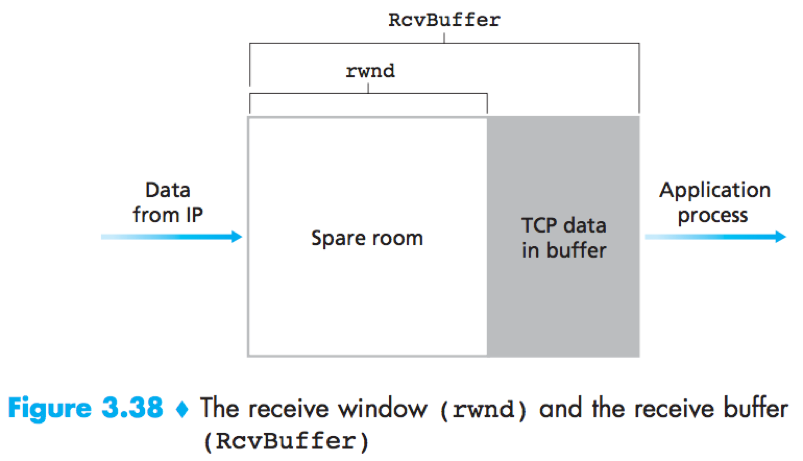
RcvBuffer: The size of the receive buffer allocated by B;
LastByteRead: The number of the last byte in the data stream read from the buffer by the application process in B;
LastByteRcvd: The number of the last byte in the data stream that has arrived from the network and has been placed in the receive buffer at B;
(LastByteRcvd-LastByteRead<=RcvBuffer)
RcvWindow = RcvBuffer-(LastByteRcvd-LastByteRead)
B maintains variable RcvWindow, placing its current value in the receive window field of every segment it sends to A.
A keeps track of variables LastByteSent and LastByteAcked, making sure throughout the connection’s life that
LastByteSent-LastByteAcked<=RcvWindow.
Problem: When B’s receive buffer become full, RcvWindow=0. Then As the receive buffer at B is emptied, No new acknowledgment segment is sent to A, and A is blocked.
Solution: The TCP specification requires A to continue to send segments with one data byte when B’s receive window is zero.
UDP does not provide flow control.
TCP connection management
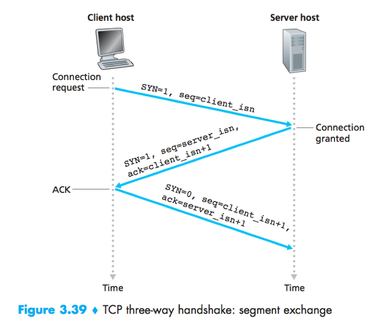
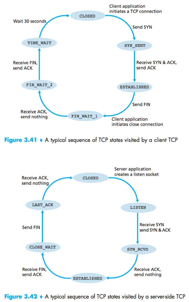
TCP three-way handshake
1) The client sends a SYN segment to the server.
SYN segment: SYN=1; sequence number=client_isn (randomly chosen by the client).
2) The server allocates buffers and variables, and sends a SYNACK segment to the to the client.
SYNACK segment: SYN=1; sequence number=server_isn (chosen by the server); acknowledgment=client_isn+1.
3) The client allocates buffers and variables, and sends a segment to the server. (SYN=0; sequence number=client_isn+1; acknowledgment=server_isn+1; may carry data.)
Once these 3 steps have been completed, the client and server can send segments (containing data, SYN=0) to each other.
e.g. packets in three-way handshake
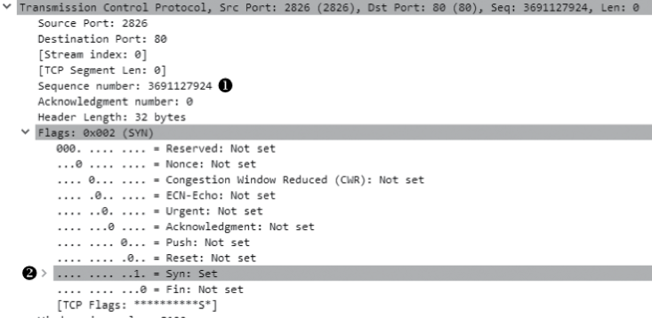
-> /Edit/Preferences/Protocols/TCP, uncheck “Relative Sequence Numbers” to see the real sequence number.
1) the initial SYN packet.
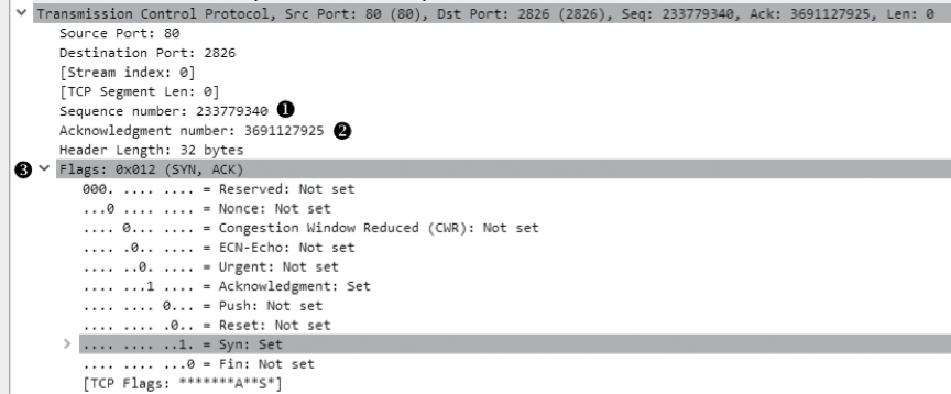
2) the SYN/ACK response. acknowledgement number = sequence number in the previous packet +1, this field specify the next sequence number the host expects to receive
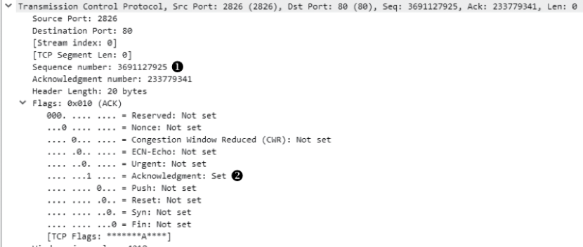
3) the final ACK. Sequence number = Acknowledgement number in the previous packet.
TCP Teardown
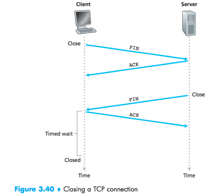
When the client decides to close the connection
1) The client sends a FIN/ACK segment (FIN and ACK are set) to the server.
2) The server sends an (ACK) acknowledgment segmentin return;
3) The server sends a (FIN) shutdown segment to the client.
4) The client sends an final (FIN/ACK) acknowledgment segment in return.
TCP Resets
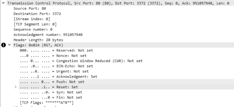
The RST flag is used to indicated a connection was closed abruptly or to refuse a connection attept.
e.g. When a host receives a TCP segment whose port numbers or source IP address do not with any of the ongoing sockets in the host, it sends a segment with RST=1 to the source, telling “I don’t have a socket for that segment, please do not resend the segment.”.
Principles of congestion control
Congestion control – throttle the sender due to congestion within the IP network.
Offered load: The rate at which the transport layer sends segments (containing original data and retransmitted data) into the network.
Congestion-control approaches can be divided into:
End-to-end congestion control: The network layer provides no explicit support to the transport layer for congestion-control purpose. (TCP must use end-to-end congestion control, since the IP layer provides no explicit feedback to the end system regarding the network congestion.)
Network-assisted congestion control: Network-layer components provide explicit feedback to the sender regarding the congestion state in the network. (e.g. ATM ABR congestion control.)
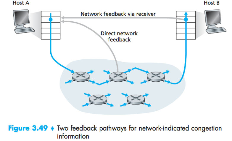
For network-assisted congestion control, congestion information is typically fed back from the network to the sender in one of two ways:
1) Direct feedback (i.e. choke packet) sent from a router to the sender;
2) Network feedback via receiver: A router marks a field in a packet to indicate congestion, and the receiver notifies the sender upon receipt of a marked packet.
ATM ABR congestion control
The ATM (available bit-rate service) ABR (asynchronous transfer mode network) protocol takes a network-assisted approach toward congestion control.
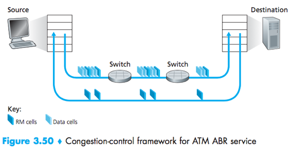
RM cells: resource-management cells interspersed with the data cells, conveys congestion-related information.
RM cells can be used to provide both direct network feedback (When an RM cell arrives at a destination, it will be turned around and sent back to the sender.) and network feedback via the receiver (A switch can generate an RM cell and send it directly to a source.).
ABR provides 3 mechanisms for signaling congestion-related information:
1) EFCI bit: The explicit forward congestion indication bit in a data cell.
A congested switch can set the EFCI bit in a data cell to 1. →
The destination check the EFCI bit in all received data cells. →
When a destination host receives an RM cell, if the most recently received data cell had the EFCI bit set to 1, then the it sets the CI bit of the RM cell to 1, and sends the RM cell back to the sender.
2) CI and NI bits: The congestion indication bit and the no increase bit in an RM cell.
A switch can set the NI bit in a passing RM cell to 1 under mild congestion, or set the CI bit to 1 under severe congestion conditions. →
When a destination host receives an RM cell, it sends the RM cell back to the sender with its CI and NI bits intact (except that CI may be set in the EFCI mechanism.).
3) ER setting: The explicit rate field in an RM cell.
A congested switch may lower the value in the ER field in a passing RM cell.
An ATM ABR source adjust the rate at which it can send cells as a function of the CI, NI and ER values in a returned RM cell.
TCP congestion control
How does a TCP sender limit its send rate?
The sender keeps track of a congestion window (cwnd) that imposes a constraint on the amount of unacknowledged data at the sender (therefore indirectly liit the send rate).
LastByteSent-LastByteAcked<=min{cwnd, rwnd}.
How does a TCP sender perceive that there is congestion?
When there is excessive congestion, then one (or more) router buffers overflows, causing a datagram to be dropped, thus results in a loss event (i.e. a timeout, or the receipt of 3 duplicate ACKs) at the sender.
TCP is self-clocking – TCP uses acknowledgments to trigger its increase in congestion window size.
How should a TCP sender determine its send rate?
TCP uses 3 guiding principles:
1. When a segment is lost, he sender should decrease its congestion window size (hence its sending rate).
2. When an ACK arrives for a previously unacknowledged segment, the sender should increase its congestion window size (hence its sending rate).
3. Bandwidth probing – The sender increases its sending rate to probe for the rate at which congestion onset begins, back off from that rate and then begins probing again to see if the congestion onset rate has changed.
TCP congestion-control algorithm has 3 major components: (1) slow start; (2) congestion avoidance; (3) fast recovery.
Slow start and congestion avoidance are mandatory component of TCP. Fast recovery is recommended but not required.
Slow start increases the size of cwnd more rapidly than congestion avoidance.
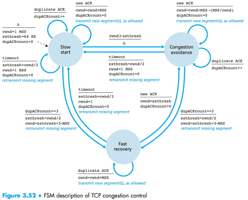
ssthresh: “slow start threshold”, a state variable.
Cwnd is added in 3 MSS for good measure to account for the triple duplicate ACKs received.
Slow start
The value of cwnd begins at 1 MSS and increases by 1 MSS every time a transmitted segment is first acknowledged. (Thus double the send rate every RTT.)
(If there is a timeout, TCP sets the value of cwnd and ssthresh, and begins the slow start process anew.)
Congestion avoidance
The value of cwnd is linearly increased by 1 MSS per RTT.
A common approach: (cwnd/MSS) segments are being sent within an RTT, so each arriving ACK increase the cwnd size by (MSS/cwnd)*MSS.
Fast recovery
The value of cwnd is increased by 1 MSS for every duplicate ACK received for the missing segment that caused TCP to enter the fast-recovery state.
TCP congestion control is often referred to as an additive-increase, ultiplicative-decrease (AIMD) form of congestion control, which gives rise to a “saw tooth” behavior.
Macroscopic description of TCP throughput
RTT-the current round-trip time; w-the window size; W-the value of w when a loss event occurs.
The TCP’s transmission rate = w/RTT.
(Assuming that RTT and W are approximately constant over the duration of the connection)
The TCP transmission rate linearly increases between W/(2·RTT) to W/RTT,
Average throughput of a connection = 0.75·W/RTT.
Repetitive process:
TCP probes for additional bandwidth by increasing w by 1 MSS each RTT until a loss event occurs (rate=W/RTT); the rate is then cut in half and then increases by MSS/RTT until it again reaches W/RTT.
L-the loss rate; RTT-the round-trip time; MSS-the maximum segment size.
Average throughput of a TCP connection = 1.22·MSS/(RTT).
The AIMD mechanism of TCP congestion control strives to provide an equal share of a bottleneck link’s bandwidth among competing TCP connection.
In many scenarios, connection establishment and slow start significantly contribute to end-to-end delay.


