
尝试自己做一个复古游戏机Arduboy学习之路 1.NANO+I2C_OLED
尝试自己做一个复古游戏机Arduboy学习之路 1.NANO+I2C_OLED

手里只有arduino micro板子和I2C接口的OLED,而Arduboy用的OLED是SPI接口的,需要修改底层。
买了SPI接口的OLED还在路上,手痒怎么办。
看到一个帖子【如果但不开,就需要FQ看】:
https://community.arduboy.com/t/arduboy-on-arduino-nano-i-c-display/5532
功能是用NANO+I2C接口的OLED做。
但是楼主说法因为换了内核,好多bug,比如内存太小有些游戏不能忘,绿色LED不会PWM控制等等。
但是还是值得尝试一下
虽然帖子不好打开,但是github在国内还是容易打开的,顺利下载了源码:
https://github.com/harbaum/Arduboy2
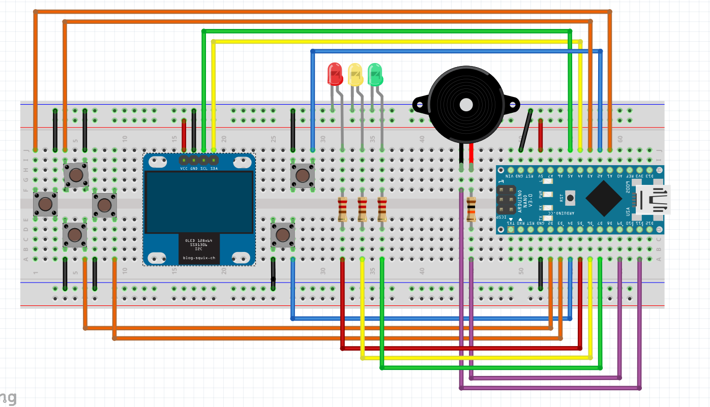
README内帖子内也有接线图,也有fritzing的原图直接可以打开
很兴奋,下载了hellowworld源码到我的micro板子上,结果没驱动起来OLED,估计底层需要修改,先挖坑
算了,先找个NANO板子试试代码吧
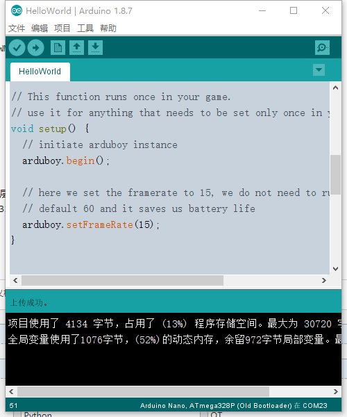
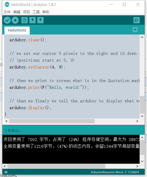
烧录成功,而且OLED也成功点亮,显示helloworld
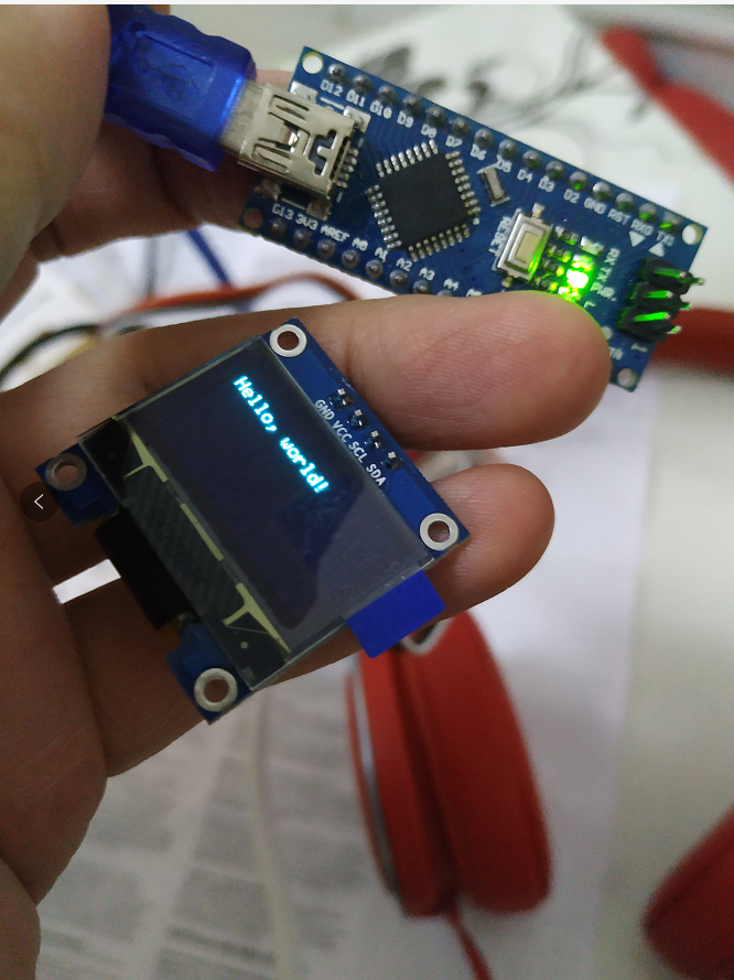
成功了一大半,其它的按键,LED,蜂鸣器都是其次,没难度。也就不研究了。
看下这个源码和官方Arduboy2的区别,看能不能修改到arduino micro板子上能用
这样和原装Arduboy对比都是ATMEGA32U4平台,只是修改一个OLED的SPI接口到I2C,应该代码不会出太多问题,只是液晶驱动速度可能会慢一些,至少可以先玩玩啊。
先看看这个源码,Arduboy2Core.h文件里面增加定义了如果内核是328p,就是当是NANO或者UNO时候的引脚定义。
/**
 * @file Arduboy2Core.h
 * \brief
 * The Arduboy2Core class for Arduboy hardware initilization and control.
 */

#ifndef ARDUBOY2_CORE_H
#define ARDUBOY2_CORE_H


#include <Arduino.h>
#include <avr/power.h>
#include <avr/sleep.h>

#ifdef __AVR_ATmega328P__
#warning SLIMBOY!
#define SLIMBOY
#endif


// main hardware compile flags

#if !defined(ARDUBOY_10) && !defined(AB_DEVKIT)
/* defaults to Arduboy Release 1.0 if not using a boards.txt file
 *
 * we default to Arduboy Release 1.0 if a compile flag has not been
 * passed to us from a boards.txt file
 *
 * if you wish to compile for the devkit without using a boards.txt
 * file simply comment out the ARDUBOY_10 define and uncomment
 * the AB_DEVKIT define like this:
 *
 *     // #define ARDUBOY_10
 *     #define AB_DEVKIT
 */
#define ARDUBOY_10   //< compile for the production Arduboy v1.0
// #define AB_DEVKIT    //< compile for the official dev kit
#endif

#ifdef SLIMBOY
#define RGB_ON HIGH   /**< For digitially setting an RGB LED on using digitalWriteRGB() */
#define RGB_OFF LOW /**< For digitially setting an RGB LED off using digitalWriteRGB() */
#else
#define RGB_ON LOW   /**< For digitially setting an RGB LED on using digitalWriteRGB() */
#define RGB_OFF HIGH /**< For digitially setting an RGB LED off using digitalWriteRGB() */
#endif

// ----- Arduboy pins -----
#ifdef ARDUBOY_10

#ifndef SLIMBOY
#define PIN_CS 12       // Display CS Arduino pin number
#define CS_PORT PORTD   // Display CS port
#define CS_BIT PORTD6   // Display CS physical bit number

#define PIN_DC 4        // Display D/C Arduino pin number
#define DC_PORT PORTD   // Display D/C port
#define DC_BIT PORTD4   // Display D/C physical bit number

#define PIN_RST 6       // Display reset Arduino pin number
#define RST_PORT PORTD  // Display reset port
#define RST_BIT PORTD7  // Display reset physical bit number
#endif

#ifdef SLIMBOY
#define RED_LED 5   /**< The pin number for the red color in the RGB LED. */
#define GREEN_LED 7 /**< The pin number for the greem color in the RGB LED. */
#define BLUE_LED 6   /**< The pin number for the blue color in the RGB LED. */

#define RED_LED_PORT PORTD
#define RED_LED_BIT PORTD5

#define GREEN_LED_PORT PORTD
#define GREEN_LED_BIT PORTD7

#define BLUE_LED_PORT PORTD
#define BLUE_LED_BIT PORTD6
#else
#define RED_LED 10   /**< The pin number for the red color in the RGB LED. */
#define GREEN_LED 11 /**< The pin number for the greem color in the RGB LED. */
#define BLUE_LED 9   /**< The pin number for the blue color in the RGB LED. */

#define RED_LED_PORT PORTB
#define RED_LED_BIT PORTB6

#define GREEN_LED_PORT PORTB
#define GREEN_LED_BIT PORTB7

#define BLUE_LED_PORT PORTB
#define BLUE_LED_BIT PORTB5
#endif

// bit values for button states
// these are determined by the buttonsState() function
#define LEFT_BUTTON _BV(5)  /**< The Left button value for functions requiring a bitmask */
#define RIGHT_BUTTON _BV(6) /**< The Right button value for functions requiring a bitmask */
#define UP_BUTTON _BV(7)    /**< The Up button value for functions requiring a bitmask */
#define DOWN_BUTTON _BV(4)  /**< The Down button value for functions requiring a bitmask */
#define A_BUTTON _BV(3)     /**< The A button value for functions requiring a bitmask */
#define B_BUTTON _BV(2)     /**< The B button value for functions requiring a bitmask */

#ifdef SLIMBOY
#define PIN_LEFT_BUTTON 15
#define LEFT_BUTTON_PORT PORTC
#define LEFT_BUTTON_PORTIN PINC
#define LEFT_BUTTON_DDR DDRC
#define LEFT_BUTTON_BIT PORTC1

#define PIN_RIGHT_BUTTON 3
#define RIGHT_BUTTON_PORT PORTD
#define RIGHT_BUTTON_PORTIN PIND
#define RIGHT_BUTTON_DDR DDRD
#define RIGHT_BUTTON_BIT PORTD3

#define PIN_UP_BUTTON 17
#define UP_BUTTON_PORT PORTC
#define UP_BUTTON_PORTIN PINC
#define UP_BUTTON_DDR DDRC
#define UP_BUTTON_BIT PORTC3

#define PIN_DOWN_BUTTON 2
#define DOWN_BUTTON_PORT PORTD
#define DOWN_BUTTON_PORTIN PIND
#define DOWN_BUTTON_DDR DDRD
#define DOWN_BUTTON_BIT PORTD2

#define PIN_A_BUTTON 4
#define A_BUTTON_PORT PORTD
#define A_BUTTON_PORTIN PIND
#define A_BUTTON_DDR DDRD
#define A_BUTTON_BIT PORTD4

#define PIN_B_BUTTON 16
#define B_BUTTON_PORT PORTC
#define B_BUTTON_PORTIN PINC
#define B_BUTTON_DDR DDRC
#define B_BUTTON_BIT PORTC2

#else

#define PIN_LEFT_BUTTON A2
#define LEFT_BUTTON_PORT PORTF
#define LEFT_BUTTON_PORTIN PINF
#define LEFT_BUTTON_DDR DDRF
#define LEFT_BUTTON_BIT PORTF5

#define PIN_RIGHT_BUTTON A1
#define RIGHT_BUTTON_PORT PORTF
#define RIGHT_BUTTON_PORTIN PINF
#define RIGHT_BUTTON_DDR DDRF
#define RIGHT_BUTTON_BIT PORTF6

#define PIN_UP_BUTTON A0
#define UP_BUTTON_PORT PORTF
#define UP_BUTTON_PORTIN PINF
#define UP_BUTTON_DDR DDRF
#define UP_BUTTON_BIT PORTF7

#define PIN_DOWN_BUTTON A3
#define DOWN_BUTTON_PORT PORTF
#define DOWN_BUTTON_PORTIN PINF
#define DOWN_BUTTON_DDR DDRF
#define DOWN_BUTTON_BIT PORTF4

#define PIN_A_BUTTON 7
#define A_BUTTON_PORT PORTE
#define A_BUTTON_PORTIN PINE
#define A_BUTTON_DDR DDRE
#define A_BUTTON_BIT PORTE6

#define PIN_B_BUTTON 8
#define B_BUTTON_PORT PORTB
#define B_BUTTON_PORTIN PINB
#define B_BUTTON_DDR DDRB
#define B_BUTTON_BIT PORTB4
#endif

#ifdef SLIMBOY
#define PIN_SPEAKER_1 9  /**< The pin number of the first lead of the speaker */
#define PIN_SPEAKER_2 11 /**< The pin number of the second lead of the speaker */

#define SPEAKER_1_PORT PORTB
#define SPEAKER_1_DDR DDRB
#define SPEAKER_1_BIT PORTB1

#define SPEAKER_2_PORT PORTB
#define SPEAKER_2_DDR DDRB
#define SPEAKER_2_BIT PORTB3

#else
#define PIN_SPEAKER_1 5  /**< The pin number of the first lead of the speaker */
#define PIN_SPEAKER_2 13 /**< The pin number of the second lead of the speaker */

#define SPEAKER_1_PORT PORTC
#define SPEAKER_1_DDR DDRC
#define SPEAKER_1_BIT PORTC6

#define SPEAKER_2_PORT PORTC
#define SPEAKER_2_DDR DDRC
#define SPEAKER_2_BIT PORTC7
#endif

// -----------------------

// ----- DevKit pins -----
#elif defined(AB_DEVKIT)

#define PIN_CS 6        // Display CS Arduino pin number
#define CS_PORT PORTD   // Display CS port
#define CS_BIT PORTD7   // Display CS physical bit number

#define PIN_DC 4        // Display D/C Arduino pin number
#define DC_PORT PORTD   // Display D/C port
#define DC_BIT PORTD4   // Display D/C physical bit number

#define PIN_RST 12      // Display reset Arduino pin number
#define RST_PORT PORTD  // Display reset port
#define RST_BIT PORTD6  // Display reset physical bit number

#define SPI_MOSI_PORT PORTB
#define SPI_MOSI_BIT PORTB2

#define SPI_SCK_PORT PORTB
#define SPI_SCK_BIT PORTB1

// map all LEDs to the single TX LED on DEVKIT
#define RED_LED 17
#define GREEN_LED 17
#define BLUE_LED 17

#define BLUE_LED_PORT PORTB
#define BLUE_LED_BIT PORTB0

// bit values for button states
// these are determined by the buttonsState() function
#define LEFT_BUTTON _BV(5)
#define RIGHT_BUTTON _BV(2)
#define UP_BUTTON _BV(4)
#define DOWN_BUTTON _BV(6)
#define A_BUTTON _BV(1)
#define B_BUTTON _BV(0)

// pin values for buttons, probably shouldn't use these
#define PIN_LEFT_BUTTON 9
#define LEFT_BUTTON_PORT PORTB
#define LEFT_BUTTON_PORTIN PINB
#define LEFT_BUTTON_DDR DDRB
#define LEFT_BUTTON_BIT PORTB5

#define PIN_RIGHT_BUTTON 5
#define RIGHT_BUTTON_PORT PORTC
#define RIGHT_BUTTON_PORTIN PINC
#define RIGHT_BUTTON_DDR DDRC
#define RIGHT_BUTTON_BIT PORTC6

#define PIN_UP_BUTTON 8
#define UP_BUTTON_PORT PORTB
#define UP_BUTTON_PORTIN PINB
#define UP_BUTTON_DDR DDRB
#define UP_BUTTON_BIT PORTB4

#define PIN_DOWN_BUTTON 10
#define DOWN_BUTTON_PORT PORTB
#define DOWN_BUTTON_PORTIN PINB
#define DOWN_BUTTON_DDR DDRB
#define DOWN_BUTTON_BIT PORTB6

#define PIN_A_BUTTON A0
#define A_BUTTON_PORT PORTF
#define A_BUTTON_PORTIN PINF
#define A_BUTTON_DDR DDRF
#define A_BUTTON_BIT PORTF7

#define PIN_B_BUTTON A1
#define B_BUTTON_PORT PORTF
#define B_BUTTON_PORTIN PINF
#define B_BUTTON_DDR DDRF
#define B_BUTTON_BIT PORTF6

#define PIN_SPEAKER_1 A2
#define SPEAKER_1_PORT PORTF
#define SPEAKER_1_DDR DDRF
#define SPEAKER_1_BIT PORTF5
// SPEAKER_2 is purposely not defined for DEVKIT as it could potentially
// be dangerous and fry your hardware (because of the devkit wiring).
//
// Reference: https://github.com/Arduboy/Arduboy/issues/108

#endif
// --------------------

// ----- Pins common on Arduboy and DevKit -----

// Unconnected analog input used for noise by initRandomSeed()
#define RAND_SEED_IN A4
#define RAND_SEED_IN_PORT PORTF
#define RAND_SEED_IN_BIT PORTF1
// Value for ADMUX to read the random seed pin: 2.56V reference, ADC1
#define RAND_SEED_IN_ADMUX (_BV(REFS0) | _BV(REFS1) | _BV(MUX0))

// SPI interface
#define SPI_MISO_PORT PORTB
#define SPI_MISO_BIT PORTB3

#define SPI_MOSI_PORT PORTB
#define SPI_MOSI_BIT PORTB2

#define SPI_SCK_PORT PORTB
#define SPI_SCK_BIT PORTB1

#define SPI_SS_PORT PORTB
#define SPI_SS_BIT PORTB0
// --------------------

// OLED hardware (SSD1306)

#define OLED_PIXELS_INVERTED 0xA7 // All pixels inverted
#define OLED_PIXELS_NORMAL 0xA6 // All pixels normal

#define OLED_ALL_PIXELS_ON 0xA5 // all pixels on
#define OLED_PIXELS_FROM_RAM 0xA4 // pixels mapped to display RAM contents

#define OLED_VERTICAL_FLIPPED 0xC0 // reversed COM scan direction
#define OLED_VERTICAL_NORMAL 0xC8 // normal COM scan direction

#define OLED_HORIZ_FLIPPED 0xA0 // reversed segment re-map
#define OLED_HORIZ_NORMAL 0xA1 // normal segment re-map

// -----

#define WIDTH 128 /**< The width of the display in pixels */
#define HEIGHT 64 /**< The height of the display in pixels */

#define COLUMN_ADDRESS_END (WIDTH - 1) & 127   // 128 pixels wide
#define PAGE_ADDRESS_END ((HEIGHT/8)-1) & 7    // 8 pages high

/** \brief
 * Eliminate the USB stack to free up code space.
 *
 * \note
 * **WARNING:** Removing the USB code will make it impossible for sketch
 * uploader programs to automatically force a reset into the bootloader!
 * This means that a user will manually have to invoke a reset in order to
 * upload a new sketch, after one without USB has be been installed.
 * Be aware that the timing for the point that a reset must be initiated can
 * be tricky, which could lead to some frustration on the user's part.
 *
 * \details
 * \parblock
 * This macro will cause the USB code, normally included in the sketch as part
 * of the standard Arduino environment, to be eliminated. This will free up a
 * fair amount of program space, and some RAM space as well, at the expense of
 * disabling all USB functionality within the sketch (except as power input).
 *
 * The macro should be placed before the `setup()` function definition:
 *
 * \code{.cpp}
 * #include <Arduboy2.h>
 *
 * Arduboy2 arduboy;
 *
 * // (Other variable declarations, etc.)
 *
 * // Eliminate the USB stack
 * ARDUBOY_NO_USB
 *
 * void setup() {
 *   arduboy.begin();
 *   // any additional setup code
 * }
 * \endcode
 *
 * As stated in the warning above, without the USB code an uploader program
 * will be unable to automatically force a reset into the bootloader to upload
 * a new sketch. The user will have to manually invoke a reset. In addition to
 * eliminating the USB code, this macro will check if the DOWN button is held
 * when the sketch first starts and, if so, will call `exitToBootloader()` to
 * start the bootloader for uploading. This makes it easier for the user than
 * having to press the reset button.
 *
 * However, to make it even more convenient for a user to invoke the bootloader
 * it is highly recommended that a sketch using this macro include a menu or
 * prompt that allows the user to press the DOWN button within the sketch,
 * which should cause `exitToBootloader()` to be called.
 *
 * At a minimum, the documentation for the sketch should clearly state that a
 * manual reset will be required, and give detailed instructions on what the
 * user must do to upload a new sketch.
 * \endparblock
 *
 * \see Arduboy2Core::exitToBootloader()
 */
#define ARDUBOY_NO_USB int main() __attribute__ ((OS_main)); \
int main() { \
  Arduboy2Core::mainNoUSB(); \
  return 0; \
}


/** \brief
 * Lower level functions generally dealing directly with the hardware.
 *
 * \details
 * This class is inherited by Arduboy2Base and thus also Arduboy2, so wouldn't
 * normally be used directly by a sketch.
 *
 * \note
 * A friend class named _Arduboy2Ex_ is declared by this class. The intention
 * is to allow a sketch to create an _Arduboy2Ex_ class which would have access
 * to the private and protected members of the Arduboy2Core class. It is hoped
 * that this may eliminate the need to create an entire local copy of the
 * library, in order to extend the functionality, in most circumstances.
 */
class Arduboy2Core
{
  friend class Arduboy2Ex;

  public:
    Arduboy2Core();

    /** \brief
     * Idle the CPU to save power.
     *
     * \details
     * This puts the CPU in _idle_ sleep mode. You should call this as often
     * as you can for the best power savings. The timer 0 overflow interrupt
     * will wake up the chip every 1ms, so even at 60 FPS a well written
     * app should be able to sleep maybe half the time in between rendering
     * it's own frames.
     */
    void static idle();

    /** \brief
     * Put the display into data mode.
     *
     * \details
     * When placed in data mode, data that is sent to the display will be
     * considered as data to be displayed.
     *
     * \note
     * This is a low level function that is not intended for general use in a
     * sketch. It has been made public and documented for use by derived
     * classes.
     *
     * \see LCDCommandMode() SPItransfer()
     */
    void static LCDDataMode();

    /** \brief
     * Put the display into command mode.
     *
     * \details
     * When placed in command mode, data that is sent to the display will be
     * treated as commands.
     *
     * See the SSD1306 controller and OLED display documents for available
     * commands and command sequences.
     *
     * Links:
     *
     * - https://www.adafruit.com/datasheets/SSD1306.pdf
     * - http://www.buydisplay.com/download/manual/ER-OLED013-1_Series_Datasheet.pdf
     *
     * \note
     * This is a low level function that is not intended for general use in a
     * sketch. It has been made public and documented for use by derived
     * classes.
     *
     * \see LCDDataMode() sendLCDCommand() SPItransfer()
     */
    void static LCDCommandMode();

    /** \brief
     * Transfer a byte to the display.
     *
     * \param data The byte to be sent to the display.
     *
     * \details
     * Transfer one byte to the display over the SPI port and wait for the
     * transfer to complete. The byte will either be interpreted as a command
     * or as data to be placed on the screen, depending on the command/data
     * mode.
     *
     * \see LCDDataMode() LCDCommandMode() sendLCDCommand()
     */
    void static SPItransfer(uint8_t data);

    /** \brief
     * Turn the display off.
     *
     * \details
     * The display will clear and be put into a low power mode. This can be
     * used to extend battery life when a game is paused or when a sketch
     * doesn't require anything to be displayed for a relatively long period
     * of time.
     *
     * \see displayOn()
     */
    void static displayOff();

    /** \brief
     * Turn the display on.
     *
     * \details
     * Used to power up and reinitialize the display after calling
     * `displayOff()`.
     *
     * \note
     * The previous call to `displayOff()` will have caused the display's
     * buffer contents to be lost. The display will have to be re-painted,
     * which is usually done by calling `display()`.
     *
     * \see displayOff()
     */
    void static displayOn();

    /** \brief
     * Get the width of the display in pixels.
     *
     * \return The width of the display in pixels.
     */
    constexpr uint8_t static width() { return WIDTH; }

    /** \brief
     * Get the height of the display in pixels.
     *
     * \return The height of the display in pixels.
     */
    constexpr uint8_t static height() { return HEIGHT; }

    /** \brief
     * Get the current state of all buttons as a bitmask.
     *
     * \return A bitmask of the state of all the buttons.
     *
     * \details
     * The returned mask contains a bit for each button. For any pressed button,
     * its bit will be 1. For released buttons their associated bits will be 0.
     *
     * The following defined mask values should be used for the buttons:
     *
     * LEFT_BUTTON, RIGHT_BUTTON, UP_BUTTON, DOWN_BUTTON, A_BUTTON, B_BUTTON
     */
    uint8_t static buttonsState();

    /** \brief
     * Paint 8 pixels vertically to the display.
     *
     * \param pixels A byte whose bits specify a vertical column of 8 pixels.
     *
     * \details
     * A byte representing a vertical column of 8 pixels is written to the
     * display at the current page and column address. The address is then
     * incremented. The page/column address will wrap to the start of the
     * display (the top left) when it increments past the end (lower right).
     *
     * The least significant bit represents the top pixel in the column.
     * A bit set to 1 is lit, 0 is unlit.
     *
     * Example:
     *
     *     X = lit pixels, . = unlit pixels
     *
     *     blank()                          paint8Pixels() 0xFF, 0, 0xF0, 0, 0x0F
     *     v TOP LEFT corner (8x9)          v TOP LEFT corner
     *     . . . . . . . . (page 1)         X . . . X . . . (page 1)
     *     . . . . . . . .                  X . . . X . . .
     *     . . . . . . . .                  X . . . X . . .
     *     . . . . . . . .                  X . . . X . . .
     *     . . . . . . . .                  X . X . . . . .
     *     . . . . . . . .                  X . X . . . . .
     *     . . . . . . . .                  X . X . . . . .
     *     . . . . . . . . (end of page 1)  X . X . . . . . (end of page 1)
     *     . . . . . . . . (page 2)         . . . . . . . . (page 2)
     */
    void static paint8Pixels(uint8_t pixels);

    /** \brief
     * Paints an entire image directly to the display from program memory.
     *
     * \param image A byte array in program memory representing the entire
     * contents of the display.
     *
     * \details
     * The contents of the specified array in program memory is written to the
     * display. Each byte in the array represents a vertical column of 8 pixels
     * with the least significant bit at the top. The bytes are written starting
     * at the top left, progressing horizontally and wrapping at the end of each
     * row, to the bottom right. The size of the array must exactly match the
     * number of pixels in the entire display.
     *
     * \see paint8Pixels()
     */
    void static paintScreen(const uint8_t *image);

    /** \brief
     * Paints an entire image directly to the display from an array in RAM.
     *
     * \param image A byte array in RAM representing the entire contents of
     * the display.
     * \param clear If `true` the array in RAM will be cleared to zeros upon
     * return from this function. If `false` the RAM buffer will remain
     * unchanged. (optional; defaults to `false`)
     *
     * \details
     * The contents of the specified array in RAM is written to the display.
     * Each byte in the array represents a vertical column of 8 pixels with
     * the least significant bit at the top. The bytes are written starting
     * at the top left, progressing horizontally and wrapping at the end of
     * each row, to the bottom right. The size of the array must exactly
     * match the number of pixels in the entire display.
     *
     * If parameter `clear` is set to `true` the RAM array will be cleared to
     * zeros after its contents are written to the display.
     *
     * \see paint8Pixels()
     */
    void static paintScreen(uint8_t image[], bool clear = false);

    /** \brief
     * Blank the display screen by setting all pixels off.
     *
     * \details
     * All pixels on the screen will be written with a value of 0 to turn
     * them off.
     */
    void static blank();

    /** \brief
     * Invert the entire display or set it back to normal.
     *
     * \param inverse `true` will invert the display. `false` will set the
     * display to no-inverted.
     *
     * \details
     * Calling this function with a value of `true` will set the display to
     * inverted mode. A pixel with a value of 0 will be on and a pixel set to 1
     * will be off.
     *
     * Once in inverted mode, the display will remain this way
     * until it is set back to non-inverted mode by calling this function with
     * `false`.
     */
    void static invert(bool inverse);

    /** \brief
     * Turn all display pixels on or display the buffer contents.
     *
     * \param on `true` turns all pixels on. `false` displays the contents
     * of the hardware display buffer.
     *
     * \details
     * Calling this function with a value of `true` will override the contents
     * of the hardware display buffer and turn all pixels on. The contents of
     * the hardware buffer will remain unchanged.
     *
     * Calling this function with a value of `false` will set the normal state
     * of displaying the contents of the hardware display buffer.
     *
     * \note
     * All pixels will be lit even if the display is in inverted mode.
     *
     * \see invert()
     */
    void static allPixelsOn(bool on);

    /** \brief
     * Flip the display vertically or set it back to normal.
     *
     * \param flipped `true` will set vertical flip mode. `false` will set
     * normal vertical orientation.
     *
     * \details
     * Calling this function with a value of `true` will cause the Y coordinate
     * to start at the bottom edge of the display instead of the top,
     * effectively flipping the display vertically.
     *
     * Once in vertical flip mode, it will remain this way until normal
     * vertical mode is set by calling this function with a value of `false`.
     *
     * \see flipHorizontal()
     */
    void static flipVertical(bool flipped);

    /** \brief
     * Flip the display horizontally or set it back to normal.
     *
     * \param flipped `true` will set horizontal flip mode. `false` will set
     * normal horizontal orientation.
     *
     * \details
     * Calling this function with a value of `true` will cause the X coordinate
     * to start at the left edge of the display instead of the right,
     * effectively flipping the display horizontally.
     *
     * Once in horizontal flip mode, it will remain this way until normal
     * horizontal mode is set by calling this function with a value of `false`.
     *
     * \see flipVertical()
     */
    void static flipHorizontal(bool flipped);

    /** \brief
     * Send a single command byte to the display.
     *
     * \param command The command byte to send to the display.
     *
     * \details
     * The display will be set to command mode then the specified command
     * byte will be sent. The display will then be set to data mode.
     * Multi-byte commands can be sent by calling this function multiple times.
     *
     * \note
     * Sending improper commands to the display can place it into invalid or
     * unexpected states, possibly even causing physical damage.
     */
    void static sendLCDCommand(uint8_t command);

    /** \brief
     * Set the light output of the RGB LED.
     *
     * \param red,green,blue The brightness value for each LED.
     *
     * \details
     * The RGB LED is actually individual red, green and blue LEDs placed
     * very close together in a single package. By setting the brightness of
     * each LED, the RGB LED can show various colors and intensities.
     * The brightness of each LED can be set to a value from 0 (fully off)
     * to 255 (fully on).
     *
     * \note
     * \parblock
     * Certain libraries that take control of the hardware timers may interfere
     * with the ability of this function to properly control the RGB LED.
     *_ArduboyPlaytune_ is one such library known to do this.
     * The digitalWriteRGB() function will still work properly in this case.
     * \endparblock
     *
     * \note
     * \parblock
     * Many of the Kickstarter Arduboys were accidentally shipped with the
     * RGB LED installed incorrectly. For these units, the green LED cannot be
     * lit. As long as the green led is set to off, setting the red LED will
     * actually control the blue LED and setting the blue LED will actually
     * control the red LED. If the green LED is turned fully on, none of the
     * LEDs will light.
     * \endparblock
     *
     * \see setRGBled(uint8_t, uint8_t) digitalWriteRGB() freeRGBled()
     */
    void static setRGBled(uint8_t red, uint8_t green, uint8_t blue);

    /** \brief
     * Set the brightness of one of the RGB LEDs without affecting the others.
     *
     * \param color The name of the LED to set. The value given should be one
     * of RED_LED, GREEN_LED or BLUE_LED.
     *
     * \param val The brightness value for the LED, from 0 to 255.
     *
     * \note
     * In order to use this function, the 3 parameter version must first be
     * called at least once, in order to initialize the hardware.
     *
     * \details
     * This 2 parameter version of the function will set the brightness of a
     * single LED within the RGB LED without affecting the current brightness
     * of the other two. See the description of the 3 parameter version of this
     * function for more details on the RGB LED.
     *
     * \see setRGBled(uint8_t, uint8_t, uint8_t) digitalWriteRGB() freeRGBled()
     */
    void static setRGBled(uint8_t color, uint8_t val);


    /** \brief
     * Relinquish analog control of the RGB LED.
     *
     * \details
     * Using the RGB LED in analog mode prevents further use of the LED in
     * digital mode. This function will restore the pins used for the LED, so
     * it can be used in digital mode.
     *
     * \see digitalWriteRGB() setRGBled()
     */
    void static freeRGBled();

    /** \brief
     * Set the RGB LEDs digitally, to either fully on or fully off.
     *
     * \param red,green,blue Use value RGB_ON or RGB_OFF to set each LED.
     *
     * \details
     * The RGB LED is actually individual red, green and blue LEDs placed
     * very close together in a single package. This 3 parameter version of the
     * function will set each LED either on or off, to set the RGB LED to
     * 7 different colors at their highest brightness or turn it off.
     *
     * The colors are as follows:
     *
     *     RED LED   GREEN_LED   BLUE_LED   COLOR
     *     -------   ---------  --------    -----
     *     RGB_OFF    RGB_OFF    RGB_OFF    OFF
     *     RGB_OFF    RGB_OFF    RGB_ON     Blue
     *     RGB_OFF    RGB_ON     RGB_OFF    Green
     *     RGB_OFF    RGB_ON     RGB_ON     Cyan
     *     RGB_ON     RGB_OFF    RGB_OFF    Red
     *     RGB_ON     RGB_OFF    RGB_ON     Magenta
     *     RGB_ON     RGB_ON     RGB_OFF    Yellow
     *     RGB_ON     RGB_ON     RGB_ON     White
     *
     * \note
     * \parblock
     * Using the RGB LED in analog mode will prevent digital control of the
     * LED. To restore the ability to control the LED digitally, use the
     * `freeRGBled()` function.
     * \endparblock
     *
     * \note
     * \parblock
     * Many of the Kickstarter Arduboys were accidentally shipped with the
     * RGB LED installed incorrectly. For these units, the green LED cannot be
     * lit. As long as the green led is set to off, turning on the red LED will
     * actually light the blue LED and turning on the blue LED will actually
     * light the red LED. If the green LED is turned on, none of the LEDs
     * will light.
     * \endparblock
     *
     * \see digitalWriteRGB(uint8_t, uint8_t) setRGBled() freeRGBled()
     */
    void static digitalWriteRGB(uint8_t red, uint8_t green, uint8_t blue);

    /** \brief
     * Set one of the RGB LEDs digitally, to either fully on or fully off.
     *
     * \param color The name of the LED to set. The value given should be one
     * of RED_LED, GREEN_LED or BLUE_LED.
     *
     * \param val Indicates whether to turn the specified LED on or off.
     * The value given should be RGB_ON or RGB_OFF.
     *
     * \details
     * This 2 parameter version of the function will set a single LED within
     * the RGB LED either fully on or fully off. See the description of the
     * 3 parameter version of this function for more details on the RGB LED.
     *
     * \see digitalWriteRGB(uint8_t, uint8_t, uint8_t) setRGBled() freeRGBled()
     */
    void static digitalWriteRGB(uint8_t color, uint8_t val);

    /** \brief
     * Initialize the Arduboy's hardware.
     *
     * \details
     * This function initializes the display, buttons, etc.
     *
     * This function is called by begin() so isn't normally called within a
     * sketch. However, in order to free up some code space, by eliminating
     * some of the start up features, it can be called in place of begin().
     * The functions that begin() would call after boot() can then be called
     * to add back in some of the start up features, if desired.
     * See the README file or documentation on the main page for more details.
     *
     * \see Arduboy2Base::begin()
     */
    void static boot();

    /** \brief
     * Allow upload when the bootloader "magic number" could be corrupted.
     *
     * \details
     * If the UP button is held when this function is entered, the RGB LED
     * will be lit and timer 0 will be disabled, then the sketch will remain
     * in a tight loop. This is to address a problem with uploading a new
     * sketch, for sketches that interfere with the bootloader "magic number".
     * The problem occurs with certain sketches that use large amounts of RAM.
     *
     * This function should be called after `boot()` in sketches that
     * potentially could cause the problem.
     *
     * It is intended to replace the `flashlight()` function when more
     * program space is required. If possible, it is more desirable to use
     * `flashlight()`, so that the actual flashlight feature isn't lost.
     *
     * \see Arduboy2Base::flashlight() boot()
     */
    void static safeMode();

    /** \brief
     * Delay for the number of milliseconds, specified as a 16 bit value.
     *
     * \param ms The delay in milliseconds.
     *
     * \details
     * This function works the same as the Arduino `delay()` function except
     * the provided value is 16 bits long, so the maximum delay allowed is
     * 65535 milliseconds (about 65.5 seconds). Using this function instead
     * of Arduino `delay()` will save a few bytes of code.
     */
    void static delayShort(uint16_t ms) __attribute__ ((noinline));

    /** \brief
     * Exit the sketch and start the bootloader
     *
     * \details
     * The sketch will exit and the bootloader will be started in command mode.
     * The effect will be similar to pressing the reset button.
     *
     * This function is intended to be used to allow uploading a new sketch,
     * when the USB code has been removed to gain more code space.
     * Ideally, the sketch would present a "New Sketch Upload" menu or prompt
     * telling the user to "Press and hold the DOWN button when the procedure
     * to upload a new sketch has been initiated". The sketch would then wait
     * for the DOWN button to be pressed and then call this function.
     *
     * \see ARDUBOY_NO_USB
     */
    void static exitToBootloader();

    // Replacement main() that eliminates the USB stack code.
    // Used by the ARDUBOY_NO_USB macro. This should not be called
    // directly from a sketch.
    void static mainNoUSB();

  protected:
    // internals
    void static setCPUSpeed8MHz();
    void static bootSPI();
    void static bootOLED();
    void static bootPins();
    void static bootPowerSaving();
};

#endif
这里面没有需要的OLED的驱动方式修改的地方,继续看Arduboy2Core.cpp
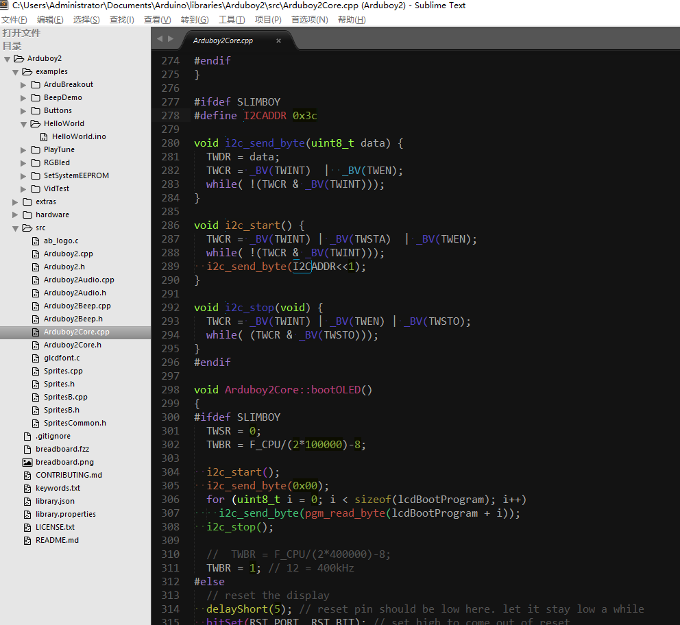
这里我们发现了增加OLED液晶驱动的部分
那么,要改到micro上,感觉主要就是这两个文件了,挖坑以后补


文章对您有帮助,开心可以打赏我,金额随意,欢迎来赏!
需要电子方面开发板/传感器/模块等硬件可以到我的淘宝店逛逛

 浙公网安备 33010602011771号