I2C Arduino 简单应用举例
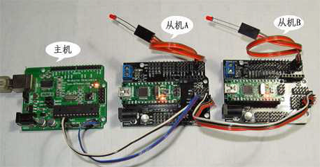
例1 多机通信

主机代码:(从编译器串口监视器发送数字1,2,3,4来控制从机的LED亮与灭)
 1 #include <Wire.h>
 2 void setup()
 3 {
 4     Wire.begin(); //启动I2C 总线,地址缺省表示为主机
 5     Serial.begin(9600); //启动串口,设置波特率为9600
 6     Serial.println("Ready"); //发送字符
 7 }
 8
 9 void loop()
10 {
11     int val;
12     if(Serial.available() > 0) //判断串口缓冲器是否有数据装入
13     {
14             val=Serial.read();  //读串口
15         if(val==49)   //1
16         {
17             Wire.beginTransmission(4);  // 与地址4 的从机连接通讯
18         Wire.write(1);  // 发送数字 1 开LED
19             Wire.endTransmission();  // 停止发送
20         Serial.println("49 OK");  // 串口上显示 49 OK 表示完成,49 表示为数字 1 的ASCII 码
21         delay(10);
22     }
23     else if(val==50)//2
24     {
25         Wire.beginTransmission(4); // 与地址4 的从机连接通讯
26       Wire. write (0); // 发送数字 0 关LED
27         Wire.endTransmission(); // 停止发送
28       Serial.println("50 OK"); // 串口上显示 50 OK 表示完成
29       delay(10);
30     }
31     else if(val==51)  //3
32     {
33         Wire.beginTransmission(5);  // 与地址5 的从机连接通讯
34         Wire. write (1);  // 发送数字 1 开LED
35         Wire.endTransmission();  // 停止发送
36        Serial.println("51 OK"); // 串口上显示 51 OK 表示完成
37         delay(10);
38     }
39     else if(val==52) //4
40     {
41         Wire.beginTransmission(5);  // 与地址5 的从机连接通讯
42         Wire.write (0);   // 发送数字 0 关LED
43         Wire.endTransmission();  // 停止发送
44         Serial.println("52 OK");  // 串口上显示 52 OK 表示完成
45         delay(10);
46     }
47     else
48     { Serial.println(val); }
49     }
50 }
从机A代码:(接收到主机发送的1点亮LED,接收到0关掉LED)
 1 #include <Wire.h>
 2 int LED = 2;
 3
 4 void setup()
 5 {
 6 Wire.begin(4);   // 设置从机地址为 4
 7 pinMode(LED,OUTPUT);   // 设置IO 口为输出模式
 8 Wire.onReceive(receiveEvent);   //从机接收主机发来的数据
 9 }
10
11 void loop()
12 { delay(100); }
13
14 void receiveEvent(int howMany)  // 接收从主机发过来的数据
15 {
16 int c = Wire.receive();  // 接收单个字节
17 if(c==1)
18 { digitalWrite(LED,HIGH); // 如果为 1 开LED }
19 else if(c==0)
20 { digitalWrite(LED,LOW); // 如果为 0 关LED }
21 }
从机B代码:(接收到主机发送的1点亮LED,接收到0关掉LED)
 1 #include <Wire.h>
 2 int LED = 2;
 3
 4 void setup()
 5 {
 6     Wire.begin(5);     // 设置从机地址为 5
 7     pinMode(LED,OUTPUT);
 8     Wire.onReceive(receiveEvent);
 9 }
10
11 void loop()
12 { delay(100);}
13
14 void receiveEvent(int howMany)
15 {
16     int c = Wire.receive();
17     if(c==1)
18     { digitalWrite(LED,HIGH); }
19     else if(c==0)
20     { digitalWrite(LED,LOW); }
21 }
例2 Master Reader/Slave Sender 从发主收信息共享
In some situations, it can be helpful to set up two (or more!) Arduino and Genuino boards to share information with each other(彼此共享信息). In this example, two boards are programmed to communicate with one another in a Master Reader/Slave Sender configuration(配置) via the I2C synchronous serial protocol(I2C同步串行协议).Several functions of Arduino's Wire Library are used to accomplish this. Arduino 1, the Master, is programmed to request, and then read, 6 bytes of data sent from the uniquely addressed Slave Arduino. Once that message is received, it can then be viewed in the Arduino Software (IDE) serial monitor window.
The I2C protocol involves using two lines to send and receive data: a serial clock pin (SCL) that the Arduino or Genuino Master board pulses at a regular interval, and a serial data pin (SDA) over which data is sent between the two devices. As the clock line changes from low to high (known as the rising edge of the clock pulse), a single bit of information - that will form in sequence the address of a specific device and a command or data - is transferred from the board to the I2Cdevice over the SDA line. When this information is sent - bit after bit -, the called upon device executes the request and transmits it's data back - if required - to the board over the same line using the clock signal still generated by the Master on SCL as timing.
Because the I2C protocol allows for each enabled device to have it's own unique address, and as both master and slave devices to take turns communicating over a single line, it is possible for your Arduino or Genuino board to communicate (in turn) with many devices, or other boards, while using just two pins of your microcontroller.
Hardware Required
- 2 Arduino or Genuino Boards
- hook-up wires
Circuit
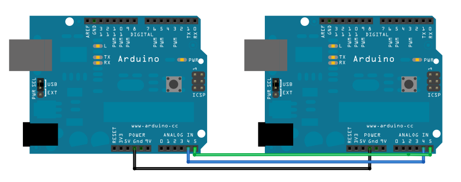
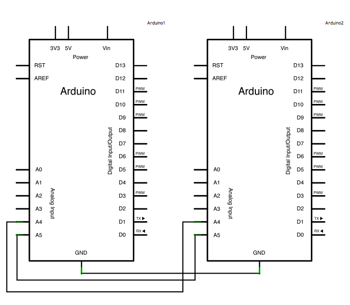
Connect pin 4 (the data, or SDA, pin) and pin 5 (the clock, or SCL, pin) on the master board to their counterparts on the slave board. Make sure that both boards share a common ground. In order to enable serial communication, the master board must be connected to your computer via USB.
If powering the boards independently is an issue, connect the 5V output of the Master to the VIN pin on the slave.

Schematic

Code for Master Reader - Program for Arduino 1
 1 #include <Wire.h>
 2
 3 void setup()
 4 {
 5   Wire.begin();        // join i2c bus (address optional for master)
 6   Serial.begin(9600);  // start serial for output
 7 }
 8
 9 void loop()
10 {
11   Wire.requestFrom(8, 6);    // request 6 bytes from slave device #8
12   while (Wire.available())
13   {
14     char c = Wire.read();   // receive a byte as character
15     Serial.print(c);         // print the character
16   }
17   delay(500);
18 }
Code for Slave Sender - Program for Arduino 2
 1 #include <Wire.h>
 2
 3 void setup()
 4 {
 5   Wire.begin(8);                  // join i2c bus with address #8
 6   Wire.onRequest(requestEvent);   // register event
 7 }
 8
 9 void loop()
10 { delay(100); }
11
12 void requestEvent()
13 {
14   Wire.write("hello ");  // respond with message of 6 bytes as expected by master
15 }
例3 Master Writer/Slave Receiver 主发从收信息共享
Hardware Required,Circuit,Schematic 同例2
Master Writer Code - Program for Arduino 1
 1 #include <Wire.h>
 2 byte x = 0;
 3
 4 void setup()
 5 {  Wire.begin(); // join i2c bus (address optional for master) }
 6
 7 void loop()
 8 {
 9   Wire.beginTransmission(8); // transmit to device #8
10   Wire.write("x is ");        // sends five bytes
11   Wire.write(x);              // sends one byte
12   Wire.endTransmission();    // stop transmitting
13   x++;
14   delay(500);
15 }
Slave Receiver Code - Program for Arduino 2
 1 #include <Wire.h>
 2
 3 void setup()
 4 {
 5   Wire.begin(8);                // join i2c bus with address #8
 6   Wire.onReceive(receiveEvent); // register event
 7   Serial.begin(9600);           // start serial for output
 8 }
 9
10 void loop()
11 { delay(100);}
12
13 void receiveEvent(int howMany)
14 {
15   while (1 < Wire.available())
16   {
17     char c = Wire.read();    // receive byte as a character
18     Serial.print(c);         // print the character
19   }
20   int x = Wire.read();     // receive byte as an integer
21   Serial.println(x);       // print the integer
22 }


