控制任务
检测编码器的脉冲并测速
电路设计

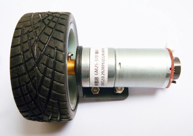
图1 直流电机带减速器和编码器

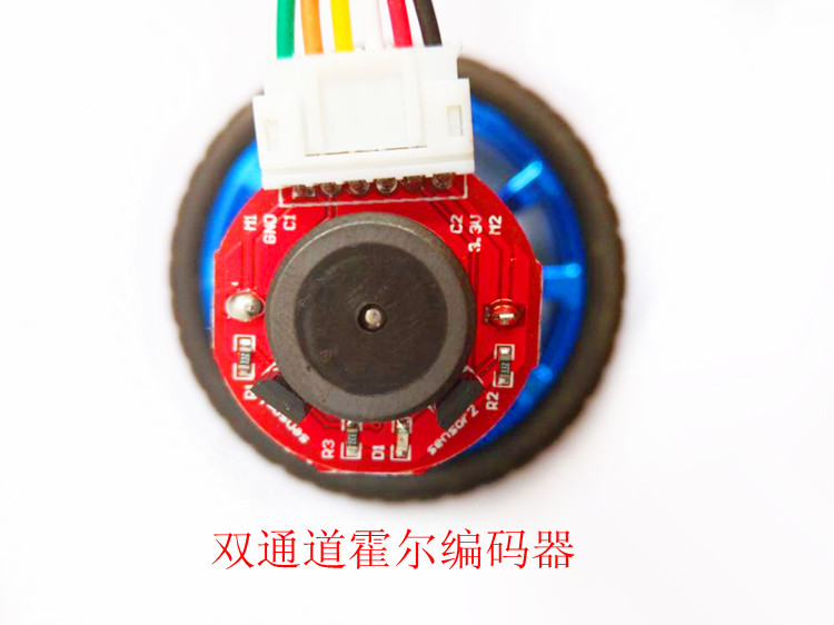
图2 编码器接线定义
编码器接线定义如下
M1:电机电源接口,绿色的
GND:编码器电源负极输入口,橙色的
C1:编码器A相输出,黄色的,接Arduino控制板2号引脚
C2:编码器B相输出,白色的,接Arduino控制板3号引脚
3.3V:编码器电源正极输入口(兼容3.3V、5V),红色的
M2:电机电源接口,黑色的,
程序设计
 1 int motor_c_ENA=6;   //控制板与驱动板的引脚连接
 2 int motor_c_IN1=8;
 3 int motor_c_IN2=7;
 4
 5 #define ENCODER_A_PIN  2     //编码器A相接控制板2号引脚,对应0号外部中断
 6 #define ENCODER_B_PIN  3     //编码器B相接控制板3号引脚,
 7 long pulse_number=0;   // 脉冲计数
 8 int rpm;
 9
10 #include <MsTimer2.h>        //定时器库的头文件
11
12 void setup()
13 {
14      pinMode(motor_c_ENA,OUTPUT);  //电机C使能和PWM调速口
15     pinMode(motor_c_IN1,OUTPUT);   //电机C控制口
16     pinMode(motor_c_IN2,OUTPUT);   //电机C控制口
17
18     MsTimer2::set(500, send);     // 中断设置函数,每 500ms 进入一次中断
19     MsTimer2::start();            //开始计时
20
21     pinMode(ENCODER_A_PIN, INPUT);
22      pinMode(ENCODER_B_PIN, INPUT);
23      attachInterrupt(0, read_quadrature, FALLING);   //EN_A脚下降沿触发中断
24     Serial.begin(9600);    //初始化Arduino串口
25 }
26
27 void loop()
28 {
29 //C加速正转
30    digitalWrite(motor_c_IN1,0);
31     digitalWrite(motor_c_IN2,1);
32     for (int a=100;a<=255;a++)
33      {
34         analogWrite(motor_c_ENA,a);
35         delay(200);
36      }
37
38 //C减速正转
39    digitalWrite(motor_c_IN1,0);
40     digitalWrite(motor_c_IN2,1);
41     for (int a=255;a>0;a--)
42     {
43         analogWrite(motor_c_ENA,a);
44         delay(200);
45      }
46 }
47
48 void send()     //速度串行传送
49 {
50      rpm=int(pulse_number/37.4);
51 //编码器精度为224线,减速器减速比为1:20,故系数=(224/(60/0.5))*20=37.4
52      Serial.print("rpm: ");
53      Serial.println(rpm, DEC);
54      pulse_number = 0;
55 }
56
57 void read_quadrature()    //编码器脉冲计数中断函数
58 {
59   if (digitalRead(ENCODER_A_PIN) == LOW)
60   {
61     if (digitalRead(ENCODER_B_PIN) == LOW)    // 查询EN_B的电平以确认正转
62     { pulse_number ++; }
63     if (digitalRead(ENCODER_B_PIN) == HIGH)     // 查询EN_B的电平以确认反转
64     { pulse_number --; }
65   }
66 }


