
【Ansys Maxwell 学习笔记】Generating the Model with the PExprt Modeling Module Ⅱ
上一篇博文地址如下:
https://www.cnblogs.com/Mr-Wangblogs/p/13131987.html
Step11:Generate the Model 输出模型
输出FEA Based Modeler 2D模型:
-
Select Modeler/FEA Based Modeler (2D)/Start Model Generation menu item or press in the Toolbar. A warning message about the parallel connection of windings is shown
选择"基于Modeler /基于FEA的Modeler(2D)/开始模型生成"菜单项,或在工具栏中按。 显示有关绕组并联的警告消息
![]()
-
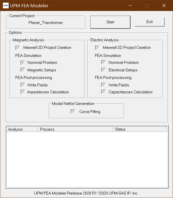
Click OK to dismiss the window. The UPM FEA Modeler window appears. The window says that Magnetic Analysis and Electric Analysis will be done using Maxwell 2D and a Curve Fitting will be run at the end of the modeling process.
单击确定以关闭该窗口。 出现" UPM FEA Modeler"窗口。 窗口显示将使用Maxwell 2D进行磁分析和电分析,并在建模过程结束时运行曲线拟合。
![]()
-
Click Start to start the modeling process. The process takes approximately 20 minutes to complete. Once the FEA-based model generation procedure is finished, a message appears, telling you that the parameter extraction is completed.
单击开始以开始建模过程。 该过程大约需要20分钟才能完成。 基于FEA的模型生成过程完成后,将出现一条消息,告诉您参数提取已完成。
-
Click OK to dismiss this message. A message appears, telling you the path to the 2D model netlist.
单击确定以消除此消息。 出现一条消息,告诉您2D模型网表的路径。
-
Click OK to dismiss this message. The UPM MGen window appears.
单击确定以消除此消息。 出现" UPM MGen"窗口。

输出结构如下图所示
Z1_1

Z1_2
Z1_3

Z1_4

Z1_5
Z1_6

Z2_2

Z2_3

Z2_4

Z2_5

Z2_6
Z3_3
Z3_4

Z3_5
Z3_6
Z4_4

Z4_5

Z4_6
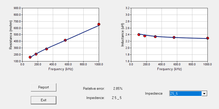
Z5_5
Z5_6

Z6_6

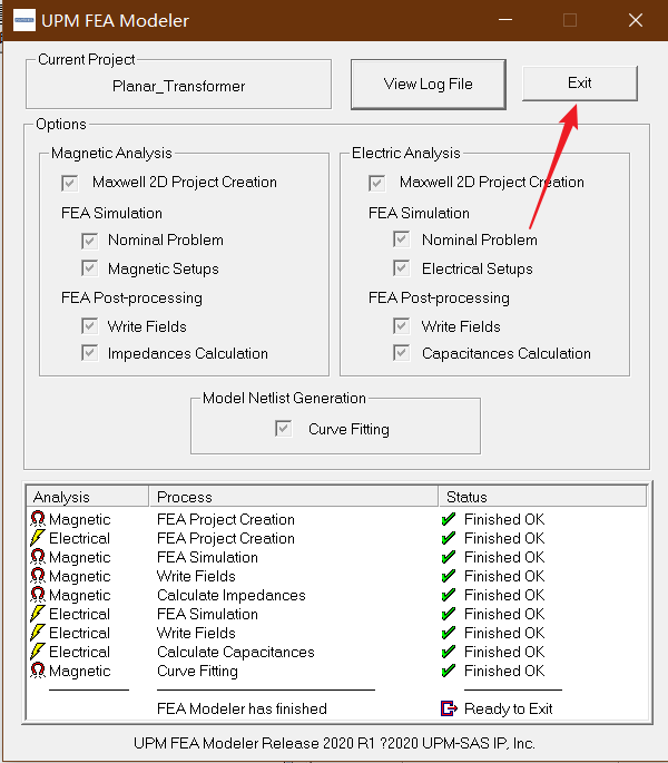
- Click Exit in the UPM MGen window to close it.
- Click Exit to close the UPM FEA Modeler window.
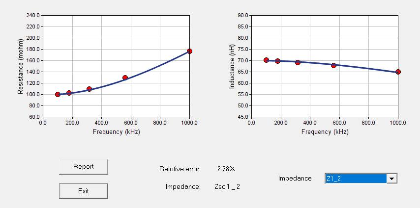
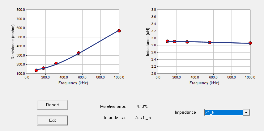
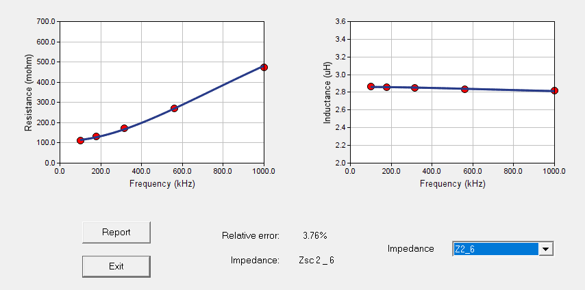
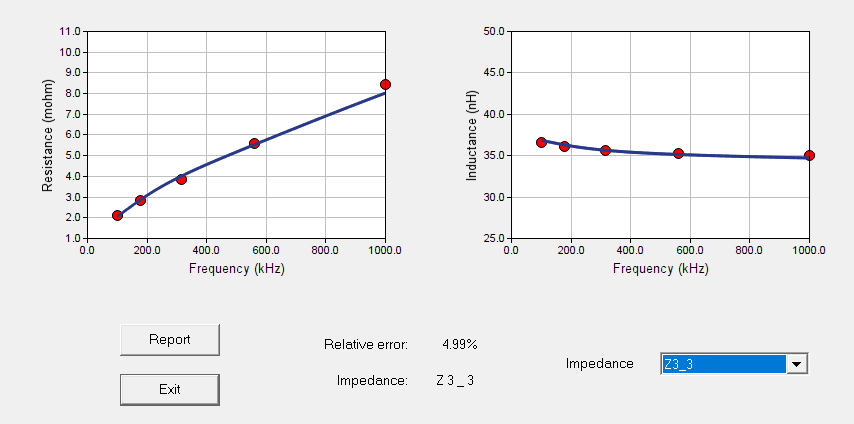
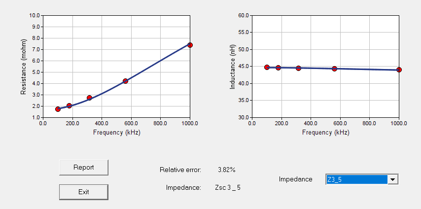
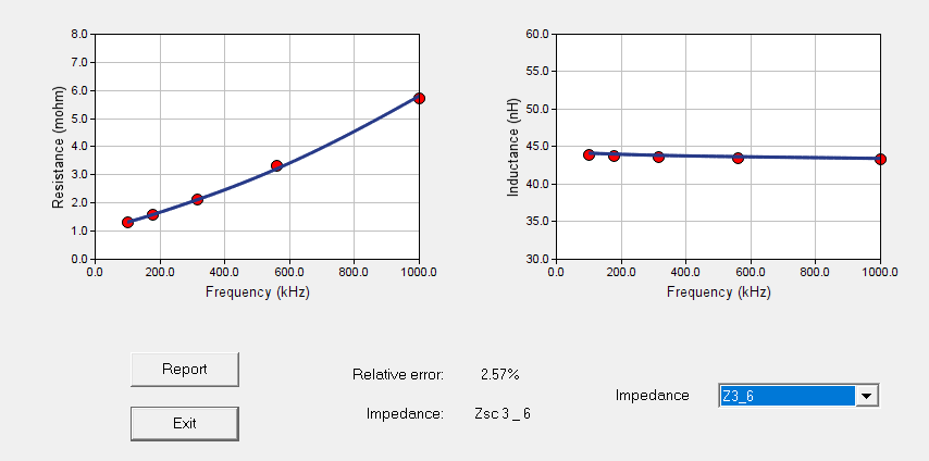
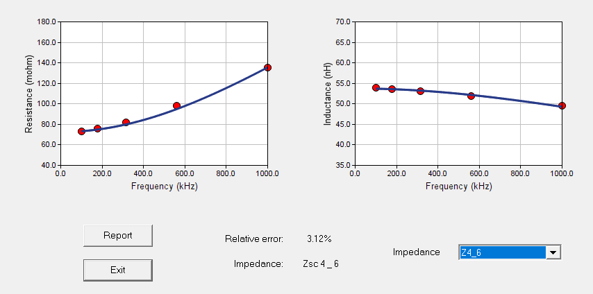
Step12:Explore the Results输出结果
Choose the Results/FEA Based (2D)/FEA Based Results menu item

Capacitive Effects:

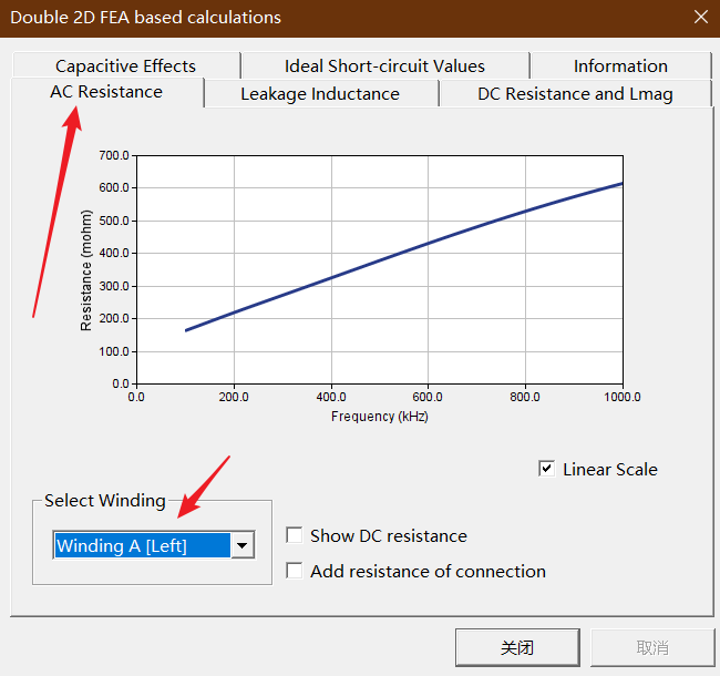
AC Resistance 信息,通过选择不同的绕组中的交流绕组信息。
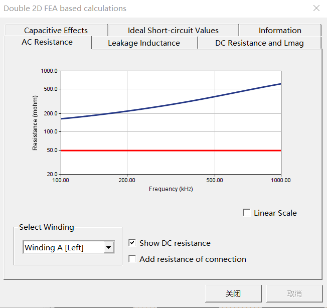
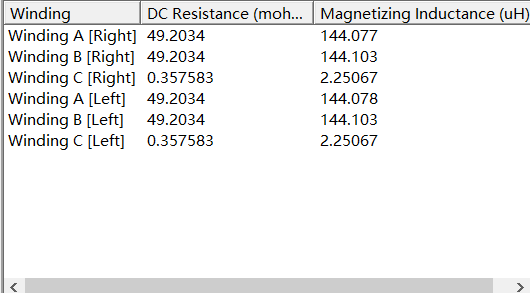
选中Show DC resistance 可以查看直流电阻信息
各绕组的直流电阻和电感信息
不同绕组的漏感信息

制作不易,如有错误或者不好理解的地方请及时留言
如需仿真源文件,请联系EMAIL:whl1457139188@outlook.com
//whl1457139188@163.com
或添加QQ:975107705
部分代码可在GitHub中下载:https://github.com/Hong-Long
请注明需要的仿真文件,建议以博客名字为邮件名

 浙公网安备 33010602011771号