HDLBits(12)2.22

1|03 电路

1|13.1 组合逻辑

1|03.1.2 数据选择器/多路复用器(Multiplexers)(MUX)

  • Mux2to1(2-to-1 multiplexers)

创建位宽为 1 的 2 对 1 数据选择器。当 sel=0 时,选择 a。当 sel=1 时,选择 b

module top_module( input a, b, sel, output out ); assign out = sel?b:a; endmodule


  • Mux2to1v(2-to-1 bus multiplexers)

创建位宽为 100 的 2 对 1 数据选择器。当 sel=0 时,选择 a。当 sel=1 时,选择 b

module top_module( input [99:0] a, b, input sel, output [99:0] out ); assign out = sel ? b : a; endmodule


  • Mux9to1(9-to-1 multiplexers)

创建位宽为 16 的 9 对 1 数据选择器。当 sel=0 时,选择 a。当 sel=1 时,选择 b,以此类推,对于未使用的情况(sel = 9 to 15)输出位为1

module top_module( input [15:0] a, b, c, d, e, f, g, h, i, input [3:0] sel, output [15:0] out ); always @(*) begin case(sel) 0: out = a ; 1: out = b ; 2: out = c ; 3: out = d ; 4: out = e ; 5: out = f ; 6: out = g ; 7: out = h ; 8: out = i ; default out = {16{1'b1}}; //复制操作符 endcase end endmodule


  • Mux256to1(256-to-1 multiplexers)

创建位宽为 1 的 256 对 1 的数据选择器,将 256 个输入全部打包成一个 256 位的输入向量。sel=0 应该选择in[0], sel=1 选择[1]中的位, sel=2 选择[2]中的位,以此类推

module top_module( input [255:0] in, input [7:0] sel, output out ); assign out = in[sel]; endmodule


  • Mux256to1v(256-to-1 4-bit multiplexers)

创建位宽为 4 的 256 对 1 的数据选择器,将 256 个 4 位输入全部打包成一个 1024 位的输入向量。sel=0 应该选择 [3:0] 中的位, sel=1 选择 [7:4] 中的位, sel=2 选择 [11:8] 中的位,以此类推

module top_module( input [1023:0] in, input [7:0] sel, output [3:0] out ); assign out = {in[sel*4+3],in[sel*4+2],in[sel*4+1],in[sel*4]}; endmodule


1|03.1.3 运算电路(Arithmetic Circuits)

  • Hadd(Half adder)

创建一个半加法器。半加器将两位相加(没有进位)得到加和和进位

module top_module( input a, b, output cout, sum ); assign sum = a ^ b ; assign cout = a & b ; endmodule


  •  Fadd(Full adder)

创建一个全加器,全加器将三位相加(包括进位)并产生加和和进位

module top_module( input a, b, cin, output cout, sum ); assign sum = a^b^cin; assign cout = a&b | a&cin | b&cin; endmodule


  • Adder3(3-bit binary adder)

创建 3 个实例来创建一个 3 位二进制波纹进位加法器。加法器将两个 3 位数字和一个进位相加产生一个 3 位加和和进位。为了鼓励实例化全加器,还要输出纹波进位加法器中每个全加器的进位。cout[2] 是最后一个全加器的最终进位,也是通常看到的进位。
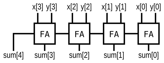
module top_module( input [2:0] a, b, input cin, output [2:0] cout, output [2:0] sum ); add1 u1 (.a(a[0]),.b(b[0]),.cin(cin),.sum(sum[0]),.cout(cout[0])); //按名称连接端口以实例化模块 add1 u1 (.a(a[1]),.b(b[1]),.cin(cout[0]),.sum(sum[1]),.cout(cout[1])); add1 u1 (.a(a[2]),.b(b[2]),.cin(cout[1]),.sum(sum[2]),.cout(cout[2])); endmodule module add1 (input a, input b, input cin, output sum, output cout); assign sum = a^b^cin; assign cout = a&b | a&cin | b&cin; endmodule
//用generate实现,直接定义逻辑,未例化模块,适用于逻辑不复杂的多模块电路 module top_module( input [2:0] a, b, input cin, output [2:0] cout, output [2:0] sum ); genvar i; generate for(i=0;i<3;i=i+1) begin:adder if(i==0) begin assign sum[i] = a[i]^b[i]^cin; assign cout[i] = a[i]&b[i] | a[i]&cin | b[i]&cin; end else begin assign sum[i]=a[i]^b[i]^cout[i-1]; assign cout[i]=a[i]&b[i] | a[i]&cout[i-1] | b[i]&cout[i-1]; end end endgenerate endmodule


  •  Adder

实现下图电路,其中FA为加法器


module top_module( input [3:0] x, input [3:0] y, output [4:0] sum); wire [3:0] cout; //未声明进位,故此处以线性信号声明进位(cout)作为中间变量 genvar i; generate //用generate实现多模块重复例化 for(i=0;i<4;i=i+1) begin:adder if(i==0) FA u1 (.a(x[0]),.b(y[0]),.sum(sum[0]),.cout(cout[0])); else FA u1 (.a(x[i]),.b(y[i]),.cin(cout[i-1]).sum(sum[i]),.cout(cout[i])); end assign sum[4] = cout[3]; endgenerate endmodule module FA (input a, input b, input cin, output sum, output cout); assign sum = a^b^cin; assign out = a&b | a&cin | b&cin; endmodule
//这种写法也是成立且正常工作的,但不确定是否有什么缺陷 module top_module ( input [3:0] x, input [3:0] y, output [4:0] sum ); assign sum = x+y; endmodule
  • signed addition overflow

假设有两个 8 位的补码,a[7:0] 和 b[7:0]。这些数字相加产生 s[7:0]。还要计算是否发生了(有符号的)溢出。

* 当两个正数相加产生负结果或两个负数相加产生正结果时,会发生有符号溢出。有几种检测溢出的方法:可以通过比较输入和输出数的符号来计算,或者从位 n 和 n-1 的进位推导出。 

module top_module ( input [7:0] a, input [7:0] b, output [7:0] s, output overflow ); assign s = a+b; assign overflow = (a[7]&b[7]&~s[7])|(~a[7]&~b[7]&s[7]); endmodule
  • 100-bit binary adder

创建一个100 位二进制加法器。加法器将两个 100 位数字和一个进位相加,产生一个 100 位加和和进位。

module top_module( input [99:0] a, b, input cin, output cout, output [99:0] sum ); assign {cout,sum} = a+b+cin; endmodule
  • 4-digit BCD adder

实例化四个 bcd_fadd 副本以创建一个4位BCD(binary-coded decimal 二进制编码的十进制)波纹进位加法器。加法器应将两个4位BCD数字(打包成16位向量)和一个进位相加,以产生一个4位加和和进位

module top_module ( input [15:0] a, b, input cin, output cout, output [15:0] sum ); wire cout1, cout2, cout3; bcd_fadd u0( .a(a[3:0]), .b(b[3:0]), .cin(cin), .cout(cout1), .sum(sum[3:0])); bcd_fadd u1( .a(a[7:4]), .b(b[7:4]), .cin(cout1), .cout(cout2), .sum(sum[7:4])); bcd_fadd u2( .a(a[11:8]), .b(b[11:8]), .cin(cout2), .cout(cout3), .sum(sum[11:8])); bcd_fadd u3( .a(a[15:12]), .b(b[15:12]), .cin(cout3), .cout(cout), .sum(sum[15:12])); endmodule

*会产生Warning:

Warning (10230): Verilog HDL assignment warning at tb_modules.sv(8): truncated value with size 32 to match size of target (4) File: /home/h/work/hdlbits.9423193/tb_modules.sv Line: 8

Truncating values occur when the right side of an assignment is wider than the left side and the upper bits are cut off. This can indicate a bug if there is a truncation you didn't expect, so check these carefully. The most common case where this isn't a bug is when you're using literals without a width (32 bits is implied), e.g., using assign a[1:0] = 1; instead of assign a[1:0] = 2'd1;

暂不知原因


__EOF__

本文作者LhTian
本文链接https://www.cnblogs.com/LhTian/p/17144470.html
关于博主:评论和私信会在第一时间回复。或者直接私信我。
版权声明:本博客所有文章除特别声明外,均采用 BY-NC-SA 许可协议。转载请注明出处!
声援博主:如果您觉得文章对您有帮助,可以点击文章右下角推荐一下。您的鼓励是博主的最大动力!
posted @   LhTian21  阅读(39)  评论(0编辑  收藏  举报
相关博文:
阅读排行:
· 开源Multi-agent AI智能体框架aevatar.ai,欢迎大家贡献代码
· Manus重磅发布:全球首款通用AI代理技术深度解析与实战指南
· 被坑几百块钱后,我竟然真的恢复了删除的微信聊天记录!
· 没有Manus邀请码?试试免邀请码的MGX或者开源的OpenManus吧
· 园子的第一款AI主题卫衣上架——"HELLO! HOW CAN I ASSIST YOU TODAY
点击右上角即可分享
微信分享提示