基于ZYNQ的OV5640摄像头的sobel算子边缘检测
1、sobel算子
Sobel 算法是像素图像边缘检测中最重要的算子之一,在机器学习、数字媒体、计算机
视觉等信息科技领域起着举足轻重的作用。在技术上,它是一个离散的一阶差分算子,用来
计算图像亮度函数的一阶梯度之近似值。在图像的任何一点使用此算子,将会产生该点对应
的梯度矢量或是其法矢。
Sobel 边缘检测通常带有方向性,可以只检测竖直边缘或垂直边缘或都检测。
实现步骤:
第一步:Sobel 提供了水平方向和垂直方向两个方向的滤波模板。设 x 方向和 y 方向
的卷积因子分别为 Gx和 Gy,模板如下所示,A 为原图像。

第二步:矩阵运算后,就得到横向灰度值 Gx 和纵向灰度值 Gy,然后通过如下公式进
行计算出该点的灰度值:

这个运算比较复杂,涉及到平方和开根(FPGA 不擅长),可以采用取近似值计算方法,对
于最终结果影响不大

第三步:设置一个阈值 threshold,对数据进行比较然后输出二值图像
2、图像灰度算法
图像数据中,含有RGB三种颜色的数据,如果一起处理的话,要很大的的运算量和位宽,为了减小运算量,可以将24位的RGB数据转化为8位的灰度图像。
虽然丢失了一些颜色等级,但是从整幅图像的整体和局部的色彩以及亮度等级分布特征来看,灰度图描述与彩色图的描述是一致的。一般有分量法、最大值法、平均值法、加权平均法四种方法对彩色图像进行灰度化。
然后本次采用的是平均值法。
将彩色图像中的三分量亮度求平均得到一个灰度值。如下:

上式中有除法,考虑到在 FPGA 中实现除法比较的消耗资源,这里在实现前可以先做
如下的近似处理。可以将上面公式乘以 3/256,这样就需要同时乘以 256/3 保证公式的正确
性。公式处理过程如下:

对 256/3 做近似取整处理,将 256/3 替换成 85,则公式变为如下。

这样式子中除以 256 就可以采用移位方法来处理,式子变为如下:

上面处理过程中使用是对 256/3 的近似处理,当然这里可以采用其他数据,比如
512/3、1024/3、2048/3 等等,基本的原则是将平均公式法中分母的 3 替换成 2 的幂次的
数,这样除法就可以使用移位的方式实现,减小 FPGA 中由于存在除法带来的资源消耗。
3、sobel算法的实现
该工程用到的算子需要三行数据才能进行,我们可以先缓存两行数据,然后接下来的输入数据加上之前缓存的两行的数据就是三行数据了,示意图如下:

缓存区像移位寄存器一样,一个周期输入一个数据和输出一个数据,可以用xilinx的RAM-base Shift Register IP核来实现。
但上面仅实现31的模板,要实现33的模板可在每行输出串联三组寄存器,以下是示意图:

然后我们就可以取寄存器组里面的值进行Sobel 算法的实现了。
4、sobel算法模块
本模块需要
- 1个16位宽1024深度的异步FIFO
- 2个16位宽1024深度的同布FIFO
- 2个8位宽400深度RAM-base Shift Register IP核
sobel_core_v1_0.v
`timescale 1ns / 1ps
//////////////////////////////////////////////////////////////////////////////////
// Company: GDUT
// Engineer: Lclone
//
// Create Date: 2023/03/27 22:04:23
// Design Name: sobel_core
// Module Name: sobel_core
// Project Name: sobel_core
// Target Devices:
// Tool Versions:
// Description:
//
// Dependencies:
//
// Revision:
// Revision 0.01 - File Created
// Additional Comments:
//
//////////////////////////////////////////////////////////////////////////////////


module sobel_core_v1_0
#   (   parameter  LINE_LENGTH = 800,       //行长度
        parameter  LINE_NUM    = 480)       //场长度
    (
        //------系统接口---------
        input        m_clk,                   //主时钟
        input        rst_n,                   //复位信号
        //------摄像头接口-------
        input        pclk,                    //像素时钟
        input [15:0] cam_data,                //图像数据输入
        input        data_valid,              //数据有效
        //------maxis接口--------
        input              m_axis_tready,
        output  reg        m_axis_tvalid,
        output      [15:0] m_axis_tdata,
        output  reg        m_axis_tlast,
        output             m_axis_tuser
    );

    //------------------cam_fifo的信号-----------------------------
    reg         cam_fifo_data_rd_en;          //cam_fifo 读使能
    reg         cam_fifo_data_rd_en_r;
    wire [15:0] cam_fifo_data_out;            //cam_fifo读出数据
    wire [ 9:0] rd_data_count;                //cam_fifo读出计数

    //------------------图像灰度算法的信号------------------------
    wire [ 9:0] sum;
    reg  [15:0] gray_r;
    wire [ 7:0] gray_8b_o;
    reg         gray_valid;
    //-------------------sbole模块信号----------------------------
    wire [ 7:0] filter_data_out;
    wire        filter_data_valid;
    //-------------------两个同步fifo的信号-----------------------
    wire [15:0] fifo_data0;
    wire [15:0] fifo_data1;
    wire [ 9:0] fifo_data_count0;
    wire [ 9:0] fifo_data_count1;
    reg  [ 9:0] out_data_count;
    reg         fifo_flag;

    //-------------------场计数信号-------------------------------
    reg  [ 8:0] line_cnt;
    reg         line_end;
    //------------------------------------------------------------
    reg m_axis_act; //m_axis活动信号

    always@(posedge m_clk or negedge rst_n) begin
        if(rst_n == 0)
            cam_fifo_data_rd_en <= 0;
        else if(rd_data_count >= LINE_LENGTH/2)//当cam_fifo里的数据大于400个的时候,就进行读取
            cam_fifo_data_rd_en <= 1;
        else if(rd_data_count <=  2) //当cam_fifo里的数据小于两个的时候,就暂停读取
            cam_fifo_data_rd_en <= 0;
        else
            cam_fifo_data_rd_en <= cam_fifo_data_rd_en;
    end
    always @(posedge m_clk) cam_fifo_data_rd_en_r <= cam_fifo_data_rd_en; //延一拍,作为写入同步fifo的写信号

    always@(posedge m_clk or negedge rst_n) begin
        if(rst_n == 0)
            m_axis_act <= 0;
        else if(fifo_data_count0 >= LINE_LENGTH/2 - 1 ) //当同步fifo0的数据有400个的时候就使axi_stream接口活动
            m_axis_act <= 1;
        else if(fifo_data_count1 <= 1 )//当同步fifo1的数据小于1个的时候就使axi_stream接口暂停活动
            m_axis_act <= 0;
        else
            m_axis_act <= m_axis_act;
    end

    always@(posedge m_clk) m_axis_tvalid <= m_axis_act;//延一拍作为tvalid信号与数据同步

    always@(posedge m_clk or negedge rst_n) begin//每行数据的最后一个拉高tlast信号
        if(rst_n == 0)
            m_axis_tlast <= 0;
        else if(out_data_count == LINE_LENGTH - 2 & m_axis_tvalid)
            m_axis_tlast <= 1;
        else
            m_axis_tlast <= 0;
    end

    always@(posedge m_clk or negedge rst_n) begin//场计数器,为给出帧同步信号而设置的。
        if(rst_n == 0)
            line_cnt <= 0;
        else if(line_cnt == LINE_NUM - 1 & out_data_count == LINE_LENGTH - 1)
            line_cnt <= 0;
        else if(out_data_count == LINE_LENGTH - 1)
            line_cnt <= line_cnt + 1'b1;
        else
            line_cnt <= line_cnt;
    end


    always@(posedge m_clk or negedge rst_n) begin//输出计数器,为给出tlast,切换fifo,给出帧同步信号而设置的。
        if(rst_n == 0)
            out_data_count <= 0;
        else if(out_data_count == LINE_LENGTH - 1)
            out_data_count <= 0;
        else if(m_axis_tvalid & m_axis_tready)
            out_data_count <= out_data_count + 1'b1;
        else
            out_data_count <= out_data_count;
    end

    always@(posedge m_clk or negedge rst_n) begin
        if(rst_n == 0)
            line_end <= 0;
        else if(line_cnt == LINE_NUM - 1 & out_data_count == LINE_LENGTH - 1)
            line_end <= 1;
        else
            line_end <= 0;
    end

    assign m_axis_tuser = (out_data_count == 0 & m_axis_tvalid & m_axis_tready & line_cnt == 0)? 1:0; //每个帧的第一个数据拉高tuser,也就是帧同步信号

    //-------------------------------------------图像灰度算法------------------------------------------------------

    assign sum = {cam_fifo_data_out[15:11],3'b0} + {cam_fifo_data_out[10:5],2'b0} + {cam_fifo_data_out[4:0],3'b0};

    always@(posedge m_clk or negedge rst_n)
    begin
    if(rst_n == 0)
        gray_r <= 16'd0;
    else if(cam_fifo_data_rd_en_r)
        gray_r <= (sum << 6)+(sum << 4)+(sum << 2)+ sum;
    else
        gray_r <= 16'd0;
    end

    assign gray_8b_o = gray_r[15:8];
    always@(posedge m_clk)
    begin
        gray_valid <= cam_fifo_data_rd_en_r;
    end

    //------------------------------------------同步fifo的数据切换--------------------------------------------------

    always@(posedge m_clk or negedge rst_n)
    begin
        if(rst_n == 0)
            fifo_flag <= 0;
        else if(out_data_count >= LINE_LENGTH - 1)
            fifo_flag <= 0;
        else if(out_data_count >= LINE_LENGTH/2 - 1)
            fifo_flag <= 1;
        else
            fifo_flag <= fifo_flag;
    end

    assign m_axis_tdata = (fifo_flag) ? fifo_data1 : fifo_data0;

    //----------------------------------------------------------------------------------------------------------

fifo_generator_1 cam_data_fifo (
  .rst(~rst_n),                      // input wire rst
  .wr_clk(pclk),                // input wire wr_clk
  .rd_clk(m_clk),                // input wire rd_clk
  .din(cam_data),                      // input wire [15 : 0] din
  .wr_en(data_valid),                  // input wire wr_en
  .rd_en(cam_fifo_data_rd_en),                  // input wire rd_en
  .dout(cam_fifo_data_out),                    // output wire [15 : 0] dout
  .full(),                    // output wire full
  .empty(),                  // output wire empty
  .rd_data_count(rd_data_count),  // output wire [9 : 0] rd_data_count
  .wr_rst_busy(),      // output wire wr_rst_busy
  .rd_rst_busy()      // output wire rd_rst_busy
);


fifo_generator_0  fifo_generator_0_inst (
  .clk(m_clk),                // input wire clk
  .srst(~rst_n),              // input wire srst
  .din(cam_fifo_data_out),                // input wire [15 : 0] din
  .wr_en(cam_fifo_data_rd_en_r),            // input wire wr_en
  .rd_en(~fifo_flag & m_axis_act & m_axis_tready),            // input wire rd_en
  .dout(fifo_data0),              // output wire [15 : 0] dout        //m_axis_tdata
  .full(),              // output wire full
  .empty(),            // output wire empty
  .data_count(fifo_data_count0)  // output wire [9 : 0] data_count
);


sobel_filter
#(  .DATA_WIDTH(8))
sobel_filter_inst
(
    .clk(m_clk),
    .reset_p(~rst_n),
    .data_in(gray_8b_o),
    .data_in_valid(gray_valid),
    .data_in_hs(1'b1),
    .data_in_vs(1'b1),
    .threshold(8'd127),
    //--------------------------
    .data_out(filter_data_out),
    .data_out_valid(filter_data_valid),
    .data_out_hs(),
    .data_out_vs()
    );


fifo_generator_0 fifo_generator_1_inst (
  .clk(m_clk),                // input wire clk
  .srst(~rst_n),              // input wire srst
  .din({{5{filter_data_out[0]}},{6{filter_data_out[0]}},{5{filter_data_out[0]}}}),// input wire [15 : 0] din
  .wr_en(filter_data_valid),            // input wire wr_en
  .rd_en(fifo_flag & m_axis_act & m_axis_tready),            // input wire rd_en
  .dout(fifo_data1),              // output wire [15 : 0] dout
  .full(),              // output wire full
  .empty(),            // output wire empty
  .data_count(fifo_data_count1)  // output wire [9 : 0] data_count
);
endmodule
sobel_filter.v
`timescale 1ns / 1ps

module sobel_filter
#(  parameter DATA_WIDTH = 8)
(
    input                          clk,
    input                          reset_p,
    input      [DATA_WIDTH - 1:0]  data_in,
    input                          data_in_valid,
    input                          data_in_hs,
    input                          data_in_vs,
    input      [DATA_WIDTH - 1:0]  threshold,
    //--------------------------
    output reg [DATA_WIDTH - 1:0]  data_out,
    output                         data_out_valid,
    output                         data_out_hs,
    output                         data_out_vs
    );

    reg  [DATA_WIDTH - 1:0] row0_col0;
    reg  [DATA_WIDTH - 1:0] row0_col1;
    reg  [DATA_WIDTH - 1:0] row0_col2;
    reg  [DATA_WIDTH - 1:0] row1_col0;
    reg  [DATA_WIDTH - 1:0] row1_col1;
    reg  [DATA_WIDTH - 1:0] row1_col2;
    reg  [DATA_WIDTH - 1:0] row2_col0;
    reg  [DATA_WIDTH - 1:0] row2_col1;
    reg  [DATA_WIDTH - 1:0] row2_col2;

    wire [DATA_WIDTH - 1:0] line0_data;
    wire [DATA_WIDTH - 1:0] line1_data;
    wire [DATA_WIDTH - 1:0] line2_data;

    reg data_in_valid_dly1;
    reg data_in_valid_dly2;
    reg data_in_valid_dly3;
    reg data_in_hs_dly1;
    reg data_in_hs_dly2;
    reg data_in_hs_dly3;
    reg data_in_vs_dly1;
    reg data_in_vs_dly2;
    reg data_in_vs_dly3;

    wire Gx_is_positive;
    wire Gy_is_positive;
    reg [DATA_WIDTH+1:0] Gx_absolute; //high bit expansion 2bit
    reg [DATA_WIDTH+1:0] Gy_absolute; //high bit expansion 2bit


always @(posedge clk or posedge reset_p) begin
 if(reset_p) begin
    row0_col0 <= 'd0;
    row0_col1 <= 'd0;
    row0_col2 <= 'd0;
    row1_col0 <= 'd0;
    row1_col1 <= 'd0;
    row1_col2 <= 'd0;
    row2_col0 <= 'd0;
    row2_col1 <= 'd0;
    row2_col2 <= 'd0;
 end
 else if(data_in_hs && data_in_vs)
 if(data_in_valid) begin
    row0_col2 <= line0_data;
    row0_col1 <= row0_col2;
    row0_col0 <= row0_col1;
    row1_col2 <= line1_data;
    row1_col1 <= row1_col2;
    row1_col0 <= row1_col1;
    row2_col2 <= line2_data;
    row2_col1 <= row2_col2;
    row2_col0 <= row2_col1;
 end
 else begin
    row0_col2 <= row0_col2;
    row0_col1 <= row0_col1;
    row0_col0 <= row0_col0;
    row1_col2 <= row1_col2;
    row1_col1 <= row1_col1;
    row1_col0 <= row1_col0;
    row2_col2 <= row2_col2;
    row2_col1 <= row2_col1;
    row2_col0 <= row2_col0;
 end
 else begin
    row0_col0 <= 'd0;
    row0_col1 <= 'd0;
    row0_col2 <= 'd0;
    row1_col0 <= 'd0;
    row1_col1 <= 'd0;
    row1_col2 <= 'd0;
    row2_col0 <= 'd0;
    row2_col1 <= 'd0;
    row2_col2 <= 'd0;
 end
end

always @(posedge clk) begin
    data_in_valid_dly1 <= data_in_valid;
    data_in_valid_dly2 <= data_in_valid_dly1;
    data_in_valid_dly3 <= data_in_valid_dly2;
    data_in_hs_dly1 <= data_in_hs;
    data_in_hs_dly2 <= data_in_hs_dly1;
    data_in_hs_dly3 <= data_in_hs_dly2;
    data_in_vs_dly1 <= data_in_vs;
    data_in_vs_dly2 <= data_in_vs_dly1;
    data_in_vs_dly3 <= data_in_vs_dly2;
end

assign data_out_valid = data_in_valid_dly3;
assign data_out_hs = data_in_hs_dly3;
assign data_out_vs = data_in_vs_dly3;

shift_register_2taps
    #(
        .DATA_WIDTH             (DATA_WIDTH)
    )
shift_register_2taps_inst
    (
        .clk                    (clk),
        .shiftin                (data_in),
        .shiftin_valid          (data_in_valid),
        .shiftout               (),
        .taps1x                 (line1_data),
        .taps0x                 (line0_data)
    );
assign line2_data = data_in;

//----------------------------------------------------
// mask x mask y
//[-1,0,1] [ 1, 2, 1]
//[-2,0,2] [ 0, 0, 0]
//[-1,0,1] [-1,-2,-1]
//----------------------------------------------------

assign Gx_is_positive = (row0_col2 + row1_col2*2 + row2_col2) >=
(row0_col0 + row1_col0*2 + row2_col0);
assign Gy_is_positive = (row0_col0 + row0_col1*2 + row0_col2) >=
(row2_col0 + row2_col1*2 + row2_col2);

always @(posedge clk or posedge reset_p) begin
    if(reset_p)
        Gx_absolute <= 'd0;
    else if(data_in_valid_dly1) begin
        if(Gx_is_positive)
            Gx_absolute <= (row0_col2 + row1_col2*2 + row2_col2) - (row0_col0 + row1_col0*2 + row2_col0);
        else
            Gx_absolute <= (row0_col0 + row1_col0*2 + row2_col0) - (row0_col2 + row1_col2*2 + row2_col2);
    end
end

always @(posedge clk or posedge reset_p) begin
    if(reset_p)
        Gy_absolute <= 'd0;
    else if(data_in_valid_dly1) begin
        if(Gy_is_positive)
            Gy_absolute <= (row0_col0 + row0_col1*2 + row0_col2) - (row2_col0 + row2_col1*2 + row2_col2);
    else
            Gy_absolute <= (row2_col0 + row2_col1*2 + row2_col2) - (row0_col0 + row0_col1*2 + row0_col2);
    end
end
//----------------------------------------------------
//result
//----------------------------------------------------
always @(posedge clk or posedge reset_p) begin
    if(reset_p)
        data_out <= 1'b0;
    else if(data_in_valid_dly2) begin
        data_out <= ((Gx_absolute+Gy_absolute)>threshold) ? 1'b0 : 1'b1;
    end
end

endmodule
5、仿真
仿真过程有复杂,调了许久,这里暂不写出。
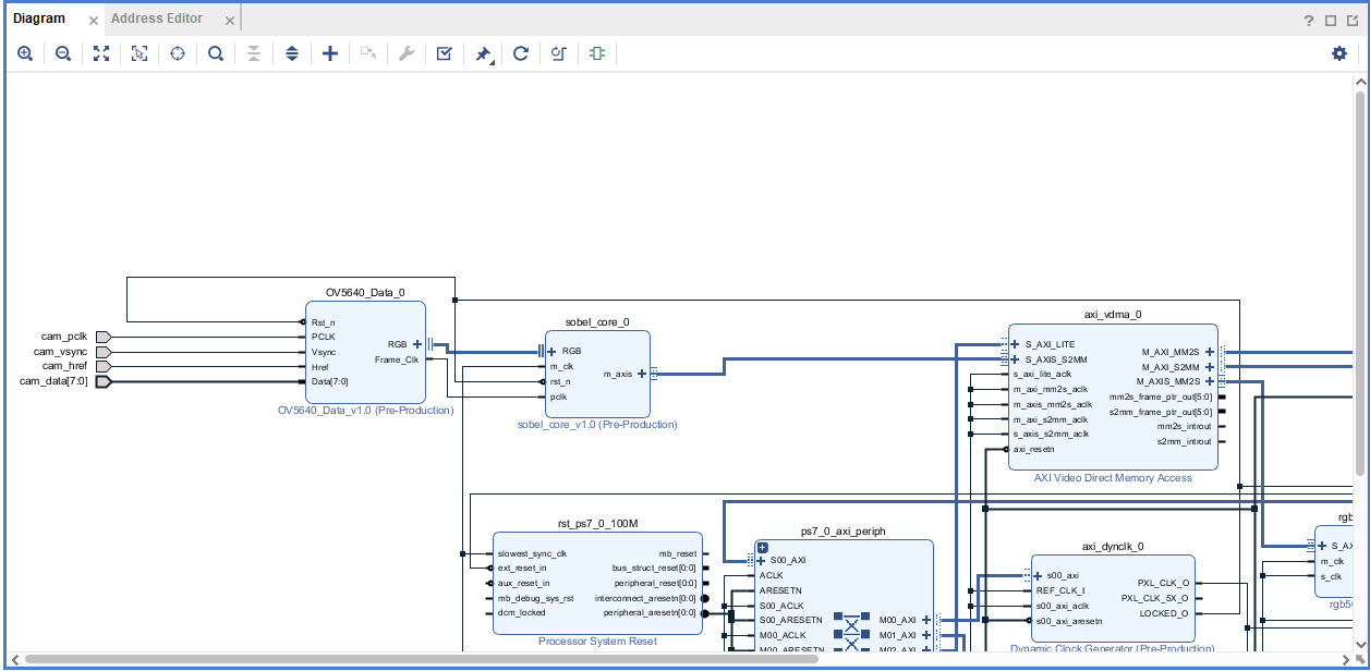
6、上板验证
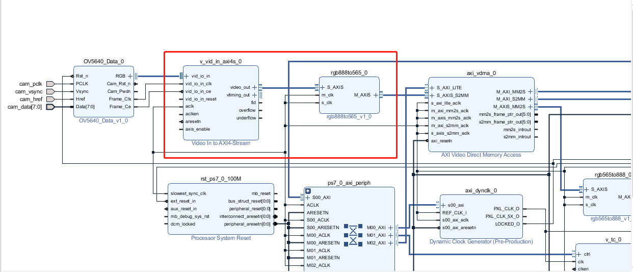
本次还是在小梅哥的OV5640_TFT这个工程的基础上进行修改,并将上面提到的模块打包成IP核,在block design里进行链接。
(1)删除红框内的模块

(2)修改OV5640_data_0 IP核
module OV5640_Data_v1_0(
    Rst_n,               //复位
    PCLK,                //像素时钟
    Vsync,               //场同步信号
    Href,                //行同步信号
    Data,                //数据

    DataValid,          //数据有效信号
    DataPixel,          //像素数据

    Frame_Clk           //时钟信号

);

    input Rst_n;            //复位
    input PCLK;             //像素时钟
    input Vsync;            //场同步信号
    input Href;             //行同步信号
    input [7:0]Data;        //数据

    output DataValid;       //数据有效信号
    output [15:0]DataPixel; //像素数据

    output Frame_Clk;//时钟信号

    reg r_Vsync;
    reg r_Href;
    reg [7:0]r_Data;

    reg [15:0]r_DataPixel;
    reg r_DataValid;
    reg [12:0]Hcount;
    reg [11:0]Vcount;
    reg [3:0]FrameCnt;

    reg Dump_Frame;

    assign DataPixel = Dump_Frame ? r_DataPixel : 24'd0;
    assign DataValid = Hcount[0] & Dump_Frame;


    //摄像头时钟使能
    //assign  Frame_Ce = ((Hcount[0]) || (!r_Href)) & Dump_Frame;//1'b1;//(r_DataValid & Dump_Frame)||(!r_DataValid);
    //assign  Frame_Ce = ((!Hcount[0]) || (!r_Href)) & Dump_Frame;//1'b1;//(r_DataValid & Dump_Frame)||(!r_DataValid);

    //时钟为像素时钟
    assign  Frame_Clk = PCLK;

    //打拍
    always@(posedge PCLK)
    begin
        r_Vsync <= Vsync;
        r_Href <= Href;
        r_Data <= Data;
    end

    //行同步信号为1时,行计数器加一(行同步信号为0时归零)
    always@(posedge PCLK or negedge Rst_n)
    if(!Rst_n)
        Hcount <= 0;
    else if(r_Href)
        Hcount <= Hcount + 1'd1;
    else
        Hcount <= 0;

    //8位转16位,赋予像素数据
    always@(posedge PCLK or negedge Rst_n)
    if(!Rst_n)
        r_DataPixel <= 0;
    else if(~Hcount[0])
        r_DataPixel <= {r_Data,Data};
    else
        r_DataPixel[7:0] <= r_Data;

    //产生数据有效信号
    always@(posedge PCLK or negedge Rst_n)
    if(!Rst_n)
        r_DataValid <= 0;
    else if(Hcount[0] && r_Href)
        r_DataValid <= 1;
    else
        r_DataValid <= 0;

    //行同步信号由0变为1时,列计数器加一(场同步信号为1时归零)
    always@(posedge PCLK or negedge Rst_n)
    if(!Rst_n)
        Vcount <= 0;
    else if(r_Vsync)
        Vcount <= 0;
    else if({r_Href,Href} == 2'b01)
        Vcount <= Vcount + 1'd1;
    else
        Vcount <= Vcount;

    //场同步信号由0变为1时,帧计数加一,最大为10
    always@(posedge PCLK or negedge Rst_n)
    if(!Rst_n)
        FrameCnt <= 0;
    else if({r_Vsync,Vsync}== 2'b01)begin
        if(FrameCnt >= 10)
            FrameCnt <= 4'd10;
        else
            FrameCnt <= FrameCnt + 1'd1;
    end
    else
        FrameCnt <= FrameCnt;

    //当计数大于等于10帧时,Dump_Frame变为1,否则为0
    always@(posedge PCLK or negedge Rst_n)
    if(!Rst_n)
        Dump_Frame <= 0;
    else if(FrameCnt >= 10)
        Dump_Frame <= 1'd1;
    else
        Dump_Frame <= 0;

endmodule
(3)添加打包好的IP核,并建立连接

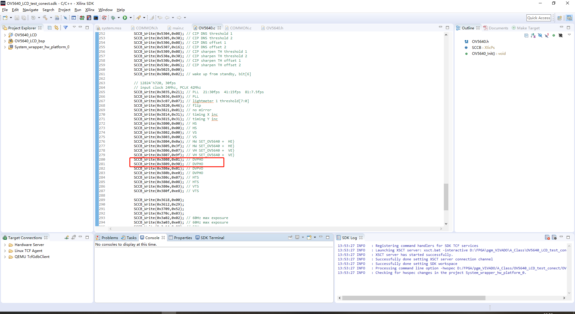
(4)修改SDK中的文件

将红框中的寄存器的值改为图片所示的值。即使摄像头输出400*480的图像。
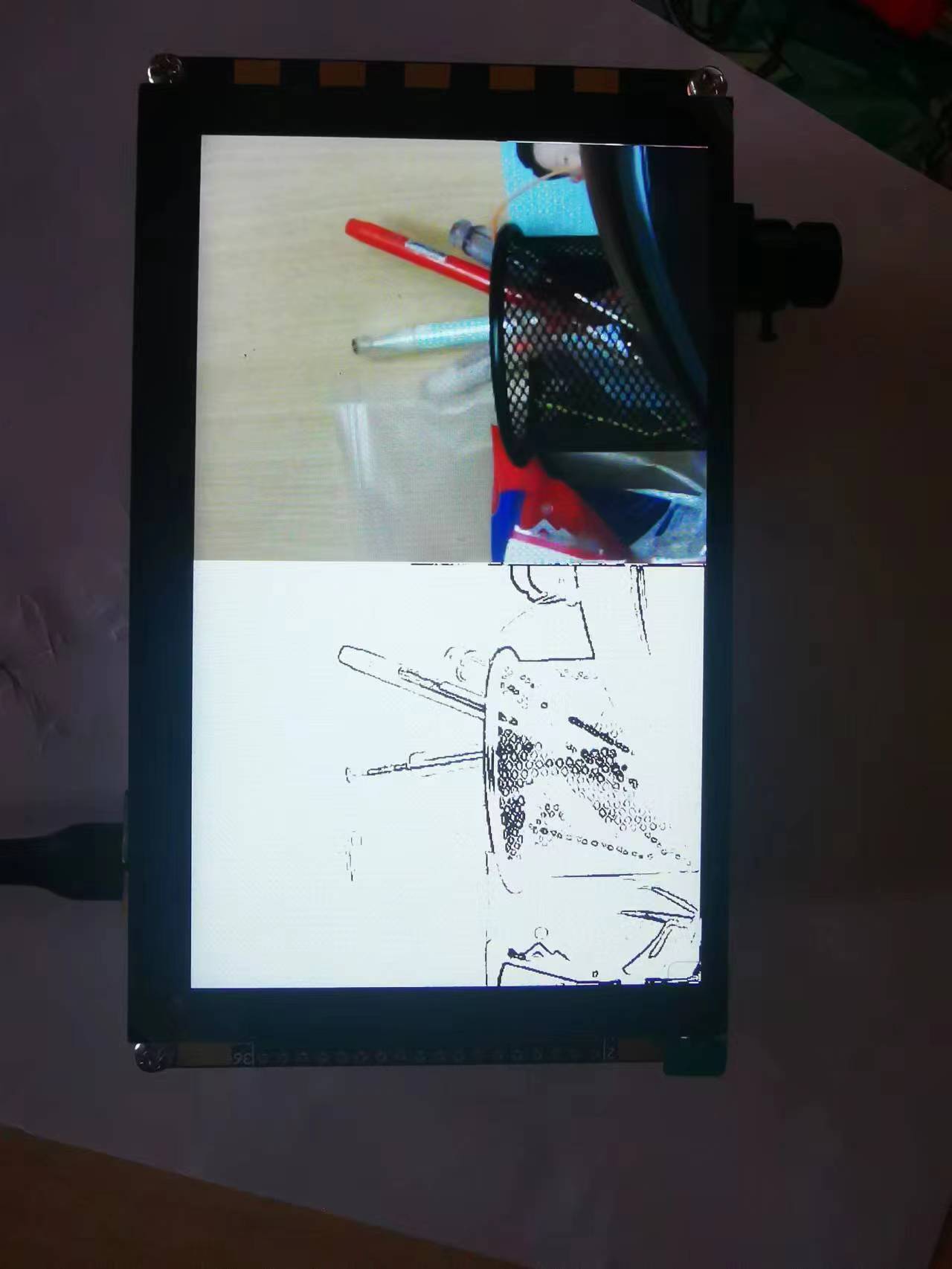
最后烧入程序,可观察到如下结果

7、可改进的地方
可以加个按键来控制sobel算法里的阈值。
(该随笔部分介绍来自小梅哥的教材,侵权删。)


 浙公网安备 33010602011771号