STC 固件程序切换
工作环境
- STC型号:STC8H3K64S4
- Keil uVision V5.20.0.0
- vscode Vision: 1.52.1
STC8H特性
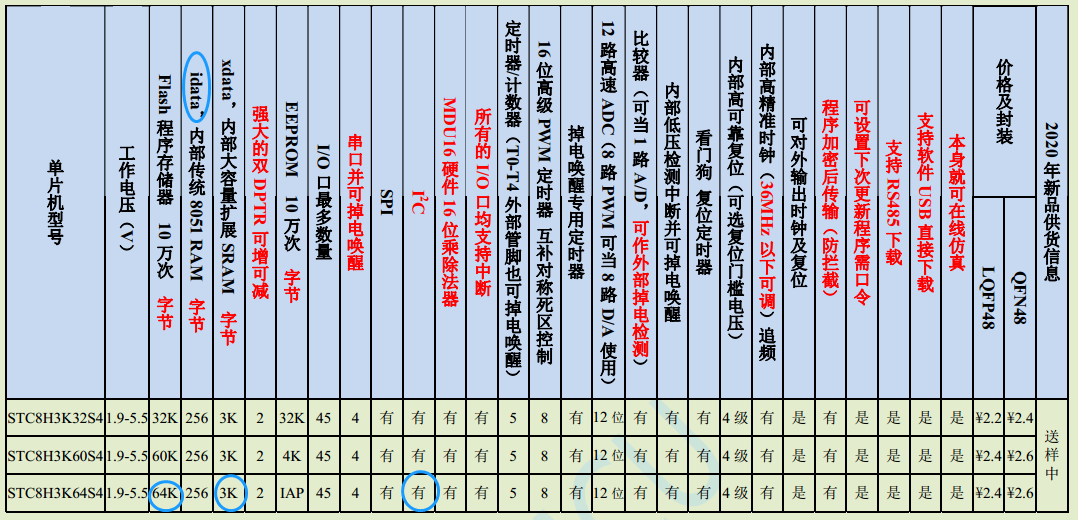
基础知识
- 单片机复位后,程序计数器(PC)的内容为 0000H,从 0000H 单元开始执行程序
- 中断服务程序的入口地址(又称中断向量)也位于程序存储器单元
- 每个中断都有一个固定的入口地址,当中断发生并得到响应后,单片机就会自动跳转到相应的中断入口地址去执行程序
- 外部中断 0(INT0)的中断服务程序的入口地址是 0003H
- 定时器/计数器 0(TIMER0)中断服务程序的入口地址是 000BH
- 外部中断 1(INT1)的中断服务程序的入口地址是 0013H
- 定时器/计数器 1(TIMER1)的中断服务程序的入口地址是 001BH
由于相邻中断入口地址的间隔区间仅仅有 8 个字节,一般情况下无法保存完整的中断服务程序,因此在中断响应的地址区域存放一条无条件转移指令,指向真正存放中断服务程序的空间去执行。
Flash 结构
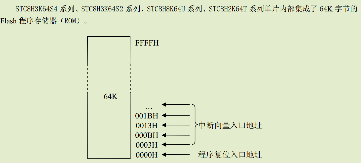
- 000H~002H 前3个字节为主程序入口跳转指令
- 003H~163H 为45个中断的跳转指令,中断号为0~44
- bin文件中,003~163H并不会全部是中断跳转指令,要看你用到的最大中断号, 中断向量表会以最大中断号而截至,如最大中断号为3,中断向量表范围为003H~001BH+2.
Flash 读写
- 用户程序只能读写EEPROM区,此区域大小,在下载时设置
- EEPROM一般放置在Flash最后面,以上面0.5K为例,EEPROM 起始地址为FE00~FFFF
- 对非空区域写入值,需要先擦除再写,擦除Flash以0.5K为单元,也就是0x200
eeprom.h
#ifndef __EEPROM_H__
#define __EEPROM_H__
void eeprom_readBuffer(int addr, char *buf, int length);
void eeprom_writeBuffer(int addr, char *buf, int length);
void IapProgram(int addr, char dat);
void IapErase(int addr);
char IapRead(int addr);
#endif
eeprom.c
#include "stc8h.h"
#include "intrins.h"


void IapIdle()
{
    IAP_CONTR = 0;                              //关闭IAP功能
    IAP_CMD = 0;                                //清除命令寄存器
    IAP_TRIG = 0;                               //清除触发寄存器
    IAP_ADDRH = 0x80;                           //将地址设置到非IAP区域
    IAP_ADDRL = 0;
}

char IapRead(int addr)
{
    char dat;

    IAP_CONTR = 0x80;                           //使能 IAP
    IAP_TPS = 12;                               //设置擦除等待参数 12MHz
    IAP_CMD = 1;                                //设置 IAP 读命令
    IAP_ADDRL = addr;                           //设置 IAP 低地址
    IAP_ADDRH = addr >> 8;                      //设置 IAP 高地址
    IAP_TRIG = 0x5a;                            //写触发命令(0x5a)
    IAP_TRIG = 0xa5;                            //写触发命令(0xa5)
    _nop_();
    dat = IAP_DATA;                             //读 IAP 数据
    IapIdle();                                  //关闭 IAP 功能

    return dat;
}

void IapProgram(int addr, char dat)
{
    IAP_CONTR = 0x80;                           //使能 IAP
    IAP_TPS = 12;                               //设置擦除等待参数 12MHz
    IAP_CMD = 2;                                //设置 IAP 写命令
    IAP_ADDRL = addr;                           //设置 IAP 低地址
    IAP_ADDRH = addr >> 8;                      //设置 IAP 高地址
    IAP_DATA = dat;                             //写 IAP 数据
    IAP_TRIG = 0x5a;                            //写触发命令(0x5a)
    IAP_TRIG = 0xa5;                            //写触发命令(0xa5)
    _nop_();
    IapIdle();                                  //关闭 IAP 功
}

void IapErase(int addr)
{
    IAP_CONTR = 0x80;                           //使能IAP
    IAP_TPS = 12;                               //设置擦除等待参数 12MHz
    IAP_CMD = 3;                                //设置IAP擦除命令
    IAP_ADDRL = addr;                           //设置IAP低地址
    IAP_ADDRH = addr >> 8;                      //设置IAP高地址
    IAP_TRIG = 0x5a;                            //写触发命令(0x5a)
    IAP_TRIG = 0xa5;                            //写触发命令(0xa5)
    _nop_();                                    //
    IapIdle();                                  //关闭IAP功能
}

void eeprom_readBuffer(int addr, char *buf, int length)
{
    int i = 0;
    for (i=0; i<length; i++) {
        buf[i] = IapRead(addr+i);
    }
}

void eeprom_writeBuffer(int addr, char *buf, int length)
{
    int i = 0;
    for (i=0; i<length; i++) {
        IapProgram(addr+i, buf[i]);
    }
}
bootloader
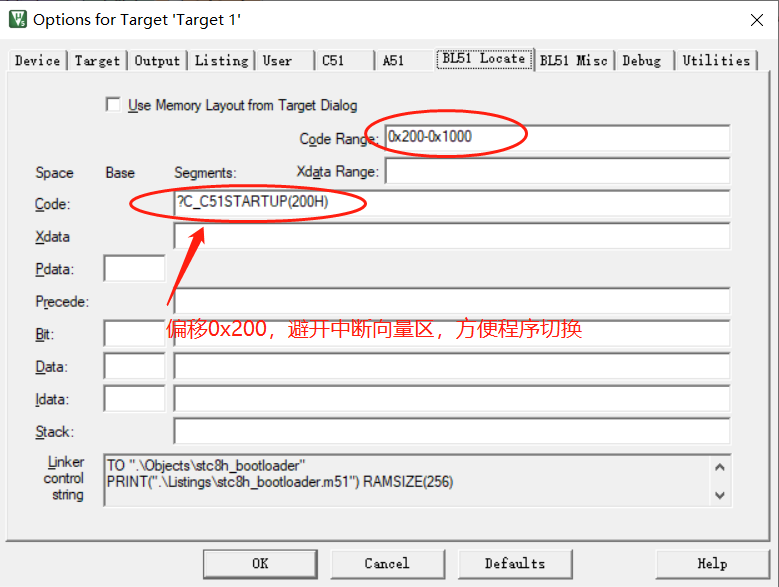
工程设置
改写STARTUP.A51
增加中断向量映射,为程序跳转准备
;Interrupt Vector Redirect
;INT0
ORG      0003H
LJMP     9003H
;Timer0
ORG      000BH
LJMP     900BH
;INT1
ORG      0013H
LJMP     9013H
;Timer1
ORG      001BH
LJMP     901BH
;UART1
ORG      0023H
LJMP     9023H
;ADC
ORG      002BH
LJMP     902BH
;LVD
ORG      0033H
LJMP     9033H
;PCA
ORG      003BH
LJMP     903BH
;UART2
ORG      0043H
LJMP     9043H
;SPI
ORG      004BH
LJMP     904BH
;INT2
ORG      0053H
LJMP     9053H
;INT3
ORG      005BH
LJMP     905BH
;Timer2
ORG      0063H
LJMP     9063H
;INT4
ORG      0083H
LJMP     9083H
;UART3
ORG      008BH
LJMP     908BH
;UART4
ORG      0093H
LJMP     9093H
;Timer3
ORG      009BH
LJMP     909BH
;Timer4
ORG      00A3H
LJMP     90A3H
;CMP
ORG      00ABH
LJMP     90ABH
;I2C
ORG      00C3H
LJMP     90C3H
;USB
ORG      00CBH
LJMP     90CBH
;PWM1
ORG      00D3H
LJMP     90D3H
;PWM2
ORG      00DDH
LJMP     90DDH
;TKSU
ORG      011BH
LJMP     911BH
;RTC
ORG      0123H
LJMP     9123H
;P0 interrupt
ORG      012BH
LJMP     912BH
;P1 interrupt
ORG      0133H
LJMP     9133H
;P2 interrupt
ORG      013BH
LJMP     913BH
;P3 interrupt
ORG      0143H
LJMP     9143H
;P4 interrupt
ORG      014BH
LJMP     914BH
;P5 interrupt
ORG      0153H
LJMP     9153H
;P6 interrupt
ORG      015BH
LJMP     915BH
;P7 interrupt
ORG      0163H
LJMP     9163H
;------------------------------------------------------------------------------

; Standard SFR Symbols
程序地址偏移
bootloader代码
为了减少不必要的麻烦,bootloader中尽量不使用中断
printf,非中断实现
以查询的方式,检查发送完成
char putchar(char c)
{
    SendData(c);
    return c;
}
/*----------------------------
发送串口数据
----------------------------*/
void SendData(BYTE dat)
{
    ACC = dat;                  //获取校验位P (PSW.0)
    if (P)                      //根据P来设置校验位
    {
#if (PARITYBIT == ODD_PARITY)
        TB8 = 0;                //设置校验位为0
#elif (PARITYBIT == EVEN_PARITY)
        TB8 = 1;                //设置校验位为1
#endif
    }
    else
    {
#if (PARITYBIT == ODD_PARITY)
        TB8 = 1;                //设置校验位为1
#elif (PARITYBIT == EVEN_PARITY)
        TB8 = 0;                //设置校验位为0
#endif
    }
    SBUF = ACC;                    //写数据到UART数据寄存器
    while (TI == 0);             //等待前面的数据发送完成
    TI = 0;
}
改变中断向量表
中断向量表范围为0000H-0200H
int changeInterruptVector(uint16_t offset)
{
    if (offset < 0x1000 || (offset&0xff) != 0) {
        return -1;
    }

    offset >>= 8;

    IapErase(0x0000);
    // bootloader 代码跳转地址
    IapProgram(0x0000, 0x02);
    IapProgram(0x0001, 0x02);
    IapProgram(0x0002, 0x00);
    ///////////////////////////////
    // INT0
    IapProgram(0x0003,   0x02);
    IapProgram(0x0003+1, 0x00|offset);
    IapProgram(0x0003+2, 0x03);
    // Timer0
    IapProgram(0x000B,   0x02);
    IapProgram(0x000B+1, 0x00|offset);
    IapProgram(0x000B+2, 0x0B);
    // INT1
    IapProgram(0x0013,   0x02);
    IapProgram(0x0013+1, 0x00|offset);
    IapProgram(0x0013+2, 0x13);
    // Timer1
    IapProgram(0x001B,   0x02);
    IapProgram(0x001B+1, 0x00|offset);
    IapProgram(0x001B+2, 0x1B);
    // UART1
    IapProgram(0x0023,   0x02);
    IapProgram(0x0023+1, 0x00|offset);
    IapProgram(0x0023+2, 0x23);
    // ADC
    IapProgram(0x002B,   0x02);
    IapProgram(0x002B+1, 0x00|offset);
    IapProgram(0x002B+2, 0x2B);
    // LVD
    IapProgram(0x0033,   0x02);
    IapProgram(0x0033+1, 0x00|offset);
    IapProgram(0x0033+2, 0x33);
    // PCA
    IapProgram(0x003B,   0x02);
    IapProgram(0x003B+1, 0x00|offset);
    IapProgram(0x003B+2, 0x3B);
    // UART2
    IapProgram(0x0043,   0x02);
    IapProgram(0x0043+1, 0x00|offset);
    IapProgram(0x0043+2, 0x43);
    // SPI
    IapProgram(0x004B,   0x02);
    IapProgram(0x004B+1, 0x00|offset);
    IapProgram(0x004B+2, 0x4B);
    // INT2
    IapProgram(0x0053,   0x02);
    IapProgram(0x0053+1, 0x00|offset);
    IapProgram(0x0053+2, 0x53);
    // INT3
    IapProgram(0x005B,   0x02);
    IapProgram(0x005B+1, 0x00|offset);
    IapProgram(0x005B+2, 0x5B);
    // Timer2
    IapProgram(0x0063,   0x02);
    IapProgram(0x0063+1, 0x00|offset);
    IapProgram(0x0063+2, 0x63);
    // INT4
    IapProgram(0x0083,   0x02);
    IapProgram(0x0083+1, 0x00|offset);
    IapProgram(0x0083+2, 0x83);
    // UART3
    IapProgram(0x008B,   0x02);
    IapProgram(0x008B+1, 0x00|offset);
    IapProgram(0x008B+2, 0x8B);
    // UART4
    IapProgram(0x0093,   0x02);
    IapProgram(0x0093+1, 0x00|offset);
    IapProgram(0x0093+2, 0x93);
    // Timer3
    IapProgram(0x009B,   0x02);
    IapProgram(0x009B+1, 0x00|offset);
    IapProgram(0x009B+2, 0x9B);
    // Timer4
    IapProgram(0x00A3,   0x02);
    IapProgram(0x00A3+1, 0x00|offset);
    IapProgram(0x00A3+2, 0xA3);
    // CMP
    IapProgram(0x00AB,   0x02);
    IapProgram(0x00AB+1, 0x00|offset);
    IapProgram(0x00AB+2, 0xAB);
    // I2C
    IapProgram(0x00C3,   0x02);
    IapProgram(0x00C3+1, 0x00|offset);
    IapProgram(0x00C3+2, 0xC3);
    // USB
    IapProgram(0x00CB,   0x02);
    IapProgram(0x00CB+1, 0x00|offset);
    IapProgram(0x00CB+2, 0xCB);
    // PWM1
    IapProgram(0x00D3,   0x02);
    IapProgram(0x00D3+1, 0x00|offset);
    IapProgram(0x00D3+2, 0xD3);
    // PWM2
    IapProgram(0x00DD,   0x02);
    IapProgram(0x00DD+1, 0x00|offset);
    IapProgram(0x00DD+2, 0xDD);
    // TKSU
    IapProgram(0x011B,   0x02);
    IapProgram(0x011B+1, 0x01|offset);
    IapProgram(0x011B+2, 0x1B);
    // RTC
    IapProgram(0x0123,   0x02);
    IapProgram(0x0123+1, 0x01|offset);
    IapProgram(0x0123+2, 0x23);
    //  P0 interrupt
    IapProgram(0x012B,   0x02);
    IapProgram(0x012B+1, 0x01|offset);
    IapProgram(0x012B+2, 0x2B);
    //  P1 interrupt
    IapProgram(0x0133,   0x02);
    IapProgram(0x0133+1, 0x01|offset);
    IapProgram(0x0133+2, 0x33);
    //  P2 interrupt
    IapProgram(0x013B,   0x02);
    IapProgram(0x013B+1, 0x01|offset);
    IapProgram(0x013B+2, 0x3B);
    //  P3 interrupt
    IapProgram(0x0143,   0x02);
    IapProgram(0x0143+1, 0x01|offset);
    IapProgram(0x0143+2, 0x43);
    //  P4 interrupt
    IapProgram(0x014B,   0x02);
    IapProgram(0x014B+1, 0x01|offset);
    IapProgram(0x014B+2, 0x4B);
    //  P5 interrupt
    IapProgram(0x0153,   0x02);
    IapProgram(0x0153+1, 0x01|offset);
    IapProgram(0x0153+2, 0x53);
    //  P6 interrupt
    IapProgram(0x015B,   0x02);
    IapProgram(0x015B+1, 0x01|offset);
    IapProgram(0x015B+2, 0x5B);
    //  P7 interrupt
    IapProgram(0x0163,   0x02);
    IapProgram(0x0163+1, 0x01|offset);
    IapProgram(0x0163+2, 0x63);

    return 0;
}
APP切换
#define USER_APP_MAGN_ADDR       0x1000
#define INTERRUPT_OFFSET_MAGN    0x2C00
#define USER_APP_BLUE_ADDR       0x3000
#define INTERRUPT_OFFSET_BLUE    0x4C00
// APP跳转函数
    void (*boot_blue)() = USER_APP_BLUE_ADDR;
    void (*boot_magn)() = USER_APP_MAGN_ADDR;

// APP切换
    changeInterruptVector(INTERRUPT_OFFSET_MAGN);
    IapErase(0xFC00);
    (*boot_magn)();
App
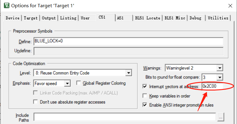
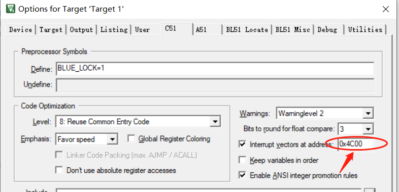
中断向量表便宜至App最后1K位置,占用0.5k,剩余0.5k可以用作程序参数区
APP1
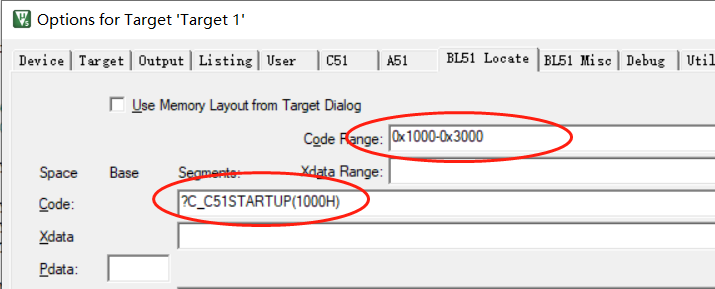
APP2
hex to bin
hex2bin下载安装
hex2bin
下载后解压,将hex2bin.exe所在的目录添加至PATH环境变量中。
keil工程设置
添加hex2bin.exe "#L.hex",如下图所示:
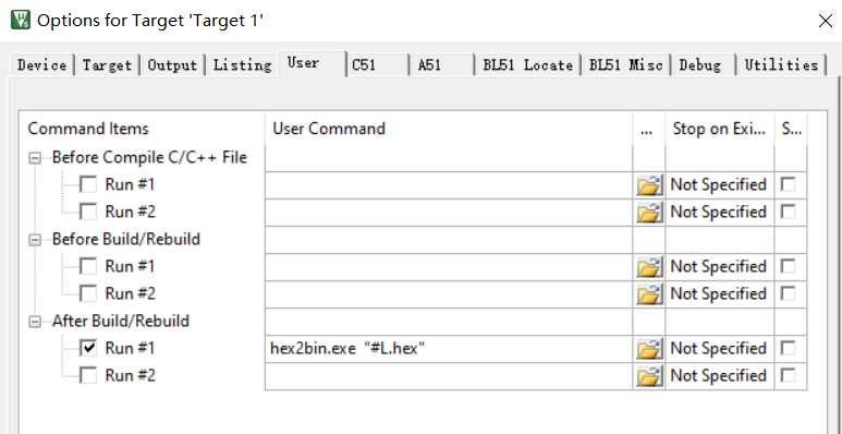
经过以上操作,编译时就会自动产生bin文件
bin文件合并
- 先添加地址靠后的APP的bin文件
- 添加其次靠后的APP,勾选插入
- 最后添加bootloader的bin文件,勾选插入
- 点击合并
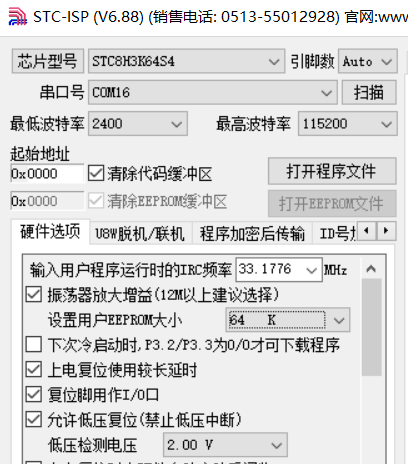
下载设置
EEPROM大小设置为64K
Todo List
- 使用脚本合成bin文件,keil添加编译后执行该脚本
- 编写脚本烧录bin文件,配合硬件实现编译后,重新上电并烧录软件
参考博客
1.KEIL-51单片机实现自定义bootloader,用于程序更新 研究
2.STC51单片机实现IAP远程升级过程分享


 浙公网安备 33010602011771号