
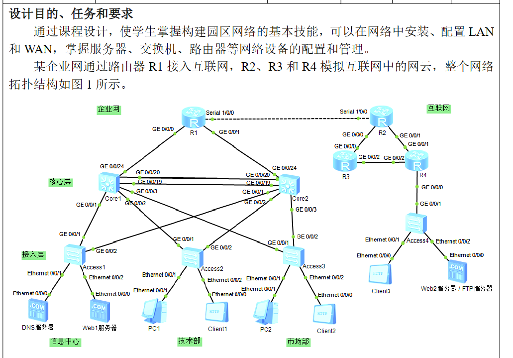
《网络技术综合实训》课程设计

1、根据设计要求,创建各个 VLAN,并完成 VLANIF 地址的配置。
Access1~Access3
[Access1]vlan batch 10 20 30
[Access1]port-group 1
[Access1-port-group-1]group-member e0/0/1 e0/0/2
[Access1-port-group-1]port link-type access
[Access1-port-group-1]port default vlan 10
[Access1-port-group-1]q
[Access1]port-group 2
[Access1-port-group-2]group-member g0/0/1 g0/0/2
[Access1-port-group-2]port link-type trunk
[Access1-port-group-2]port trunk allow-pass vlan all
Core1~Core2
[Core1]vlan batch 10 20 30 40
[Core1]port-group 1
[Core1-port-group-1]group-member g0/0/1 to g0/0/3
[Core1-port-group-1]port link-type trunk
[Core1-port-group-1]port trunk allow-pass vlan all
[Core1-port-group-1]q
[Core1]int g0/0/24
[Core1-GigabitEthernet0/0/24]port link-type access
[Core1-GigabitEthernet0/0/24]port default vlan 40

[Core1]int vlan 10
[Core1-Vlanif10]ip address 10.19.1.253 24
[Core1-Vlanif10]q
[Core1]int vlan 20
[Core1-Vlanif20]ip address 10.19.2.253 24
[Core1-Vlanif20]q
[Core1]int vlan 30
[Core1-Vlanif30]ip address 10.19.3.253 24
[Core1-Vlanif30]q
[Core1]int vlan 40
[Core1-Vlanif40]ip address 10.19.4.1 24
AR1
[AR1]int g0/0/0
[AR1-GigabitEthernet0/0/0]ip add 10.19.4.2 24
[AR1-GigabitEthernet0/0/0]int g0/0/1
[AR1-GigabitEthernet0/0/1]ip add 10.19.5.2 24
2、采用链路聚合技术提高核心层交换机之间的链路带宽。
Core1~Core2
[Core1]lacp priority 1000
[Core1]int Eth-Trunk 1
[Core1-Eth-Trunk1]trunkport GigabitEthernet 0/0/19 to 0/0/20
[Core1-Eth-Trunk1]port link-type trunk
[Core1-Eth-Trunk1]port trunk allow-pass vlan all
3、在接入层交换机和核心层交换机上进行 MSTP 协议的配置,要求 Core1 为 VLAN10的根桥,Core2 为 VLAB20 和 VLAN30 的根桥,MST 域名为姓名全拼。
Core1
[Core1]stp mode mstp
[Core1]stp region-configuration
[Core1-mst-region]region-name wangjiasheng
[Core1-mst-region]revision-level 1
[Core1-mst-region]instance 10 vlan 10
[Core1-mst-region]instance 20 vlan 20
[Core1-mst-region]instance 30 vlan 30
[Core1-mst-region]active region-configuration
[Core1-mst-region]q
[Core1]stp instance 10 root primary
[Core1]stp instance 20 root secondary
[Core1]stp instance 30 root secondary
Core2
[Core2]stp mode mstp
[Core2]stp region-configuration
[Core2-mst-region]region-name wangjiasheng
[Core2-mst-region]revision-level 1
[Core1-mst-region]instance 10 vlan 10
[Core1-mst-region]instance 20 vlan 20
[Core1-mst-region]instance 30 vlan 30
[Core2-mst-region]active region-configuration
[Core2-mst-region]q
[Core2]stp instance 20 root primary
[Core2]stp instance 10 root secondary
[Core1]stp instance 30 root primary
Access1~Access3
[Huawei]stp mode mstp
[Huawei]stp region-configuration
[Huawei-mst-region]region-name wangjiasheng
[Huawei-mst-region]revision-level 1
[Huawei-mst-region]instance 10 vlan 10
[Huawei-mst-region]active region-configuration
4、在核心层交换机上实现 VRRP 协议的配置,要求信息中心向外访问时流量优先经过 Core1,技术部和市场部向外访问时流量优先经过 Core2。
Core1
[Core1]int Vlanif 10
[Core1-Vlanif10]vrrp vrid 10 virtual-ip 10.19.1.254
[Core1-Vlanif10]vrrp vrid 10 priority 105
[Core1-Vlanif10]vrrp vrid 10 track interface g0/0/1 reduced 30
[Core1-Vlanif10]vrrp vrid 10 track interface g0/0/24 reduced 30
[Core1-Vlanif10]int Vlanif 20
[Core1-Vlanif20]vrrp vrid 20 virtual-ip 10.19.2.254
[Core1-Vlanif20]int Vlanif 30
[Core1-Vlanif30]vrrp vrid 30 virtual-ip 10.19.3.254
Core2
[Core2]int Vlanif 10
[Core2-Vlanif10]vrrp vrid 10 virtual-ip 10.19.1.254
[Core2]int Vlanif 20
[Core2-Vlanif20]vrrp vrid 20 virtual-ip 10.19.2.254
[Core2-Vlanif20]vrrp vrid 20 priority 105
[Core2-Vlanif20]vrrp vrid 20 track interface g0/0/2 reduced 30
[Core1-Vlanif20]vrrp vrid 20 track interface g0/0/24 reduced 30
[Core2-Vlanif20]int Vlanif 30
[Core2-Vlanif30]vrrp vrid 30 virtual-ip 10.19.3.254
[Core2-Vlanif30]vrrp vrid 30 priority 105
[Core2-Vlanif30]vrrp vrid 30 track interface g0/0/3 reduced 30
[Core1-Vlanif30]vrrp vrid 30 track interface g0/0/24 reduced 30
5、在核心层交换机和路由器 R1 上配置静态路由,保障企业网主机可以互通。在 R1上配置默认路由,接入互联网。
Core1
[Huawei]ip route-static 0.0.0.0 0.0.0.0 10.19.4.2
Core1
[Huawei]ip route-static 0.0.0.0 0.0.0.0 10.19.5.2
AR1
[AR1]ip route-static 10.19.1.0 24 10.19.4.1
[AR1]ip route-static 10.19.1.0 24 10.19.5.1 preference 80
[AR1]ip route-static 10.19.2.0 24 10.19.5.1
[AR1]ip route-static 10.19.2.0 24 10.19.4.1 preference 80
[AR1]ip route-static 10.19.3.0 24 10.19.4.1 preference 80
[AR1]ip route-static 10.19.3.0 24 10.19.5.1
[AR1]int s1/0/0
[AR1-Serial1/0/0]ip add 200.19.1.1 24
ip route-static 0.0.0.0 0.0.0.0 200.19.1.2
AR2
ip route-static 0.0.0.0 0 200.19.1.1
6、在路由器 R4 上使用单臂路由技术实现 VLAN60 和 VLAN70 之间的通信。
Access4
[Access4]vlan batch 60 70
[Access4]int e0/0/1
[Access4-Ethernet0/0/1]port link-type access
[Access4-Ethernet0/0/1]port default vlan 60
[Access4-Ethernet0/0/1]int e0/0/2
[Access4-Ethernet0/0/2]port link-type access
[Access4-Ethernet0/0/2]port default vlan 70
[Access4]int g0/0/1
[Access4-GigabitEthernet0/0/1]port link-type trunk
[Access4-GigabitEthernet0/0/1]port trunk allow-pass vlan 60 70
AR4
[AR4]int g0/0/0.1
[AR4-GigabitEthernet0/0/0.1]dot1q termination vid 60
[AR4-GigabitEthernet0/0/0.1]ip address 200.19.6.254 24
[AR4-GigabitEthernet0/0/0.1]arp broadcast enable
[AR4-GigabitEthernet0/0/0.1]int g0/0/0.2
[AR4-GigabitEthernet0/0/0.2]dot1q termination vid 70
[AR4-GigabitEthernet0/0/0.2]ip address 200.19.7.254 24
[AR4-GigabitEthernet0/0/0.2]arp broadcast enable
7、配置路由器 R2、R3 和 R4 运行 OSPF 协议。
AR2
[AR2]int s1/0/0
[AR2-Serial1/0/0]ip add 200.19.1.2 24
[AR2-Serial1/0/0]int g0/0/0
[AR2-GigabitEthernet0/0/0]ip add 200.19.2.1 24
[AR2-GigabitEthernet0/0/0]int g0/0/1
[AR2-GigabitEthernet0/0/1]ip add 200.19.3.1 24

[AR2-GigabitEthernet0/0/1]ospf 1
[AR2-ospf-1]area 0
[AR2-ospf-1-area-0.0.0.0]network 200.19.1.0 0.0.0.255
[AR2-ospf-1-area-0.0.0.0]network 200.19.2.0 0.0.0.255
[AR2-ospf-1-area-0.0.0.0]network 200.19.3.0 0.0.0.255
AR3
int g0/0/0
ip add 200.19.2.2 24
[AR3]int g0/0/0
[AR3-GigabitEthernet0/0/0]ip add 200.19.2.2 24
[AR3-GigabitEthernet0/0/0]int g0/0/2
[AR3-GigabitEthernet0/0/2]ip add 200.19.4.1 24
[AR3-GigabitEthernet0/0/2]ospf 1
[AR3-ospf-1]area 0
[AR3-ospf-1-area-0.0.0.0]network 200.19.2.0 0.0.0.255
[AR3-ospf-1-area-0.0.0.0]network 200.19.4.0 0.0.0.255
AR4
[AR4]int g0/0/1
[AR4-GigabitEthernet0/0/1]ip add 200.19.3.2 24
[AR4-GigabitEthernet0/0/1]int g0/0/2
[AR4-GigabitEthernet0/0/2]ip add 200.19.4.4 24
[AR4-GigabitEthernet0/0/2]ospf 1
[AR4-ospf-1]area 0
[AR4-ospf-1-area-0.0.0.0]network 200.19.3.0 0.0.0.255
[AR4-ospf-1-area-0.0.0.0]network 200.19.4.0 0.0.0.255
[AR4-ospf-1-area-0.0.0.0]network 200.19.6.0 0.0.0.255
[AR4-ospf-1-area-0.0.0.0]network 200.19.7.0 0.0.0.255
8、路由器 R1 与 R2 之间封装 PPP 协议,使用 CHAP 单向认证。R2 为认证方,R1 为被认证方,用户名为姓名全拼。
AR1
[Huawei]int s1/0/0
[Huawei-Serial4/0/0]link-protocol ppp
[Huawei-Serial4/0/0]remote address 200.19.1.2
[Huawei-Serial4/0/0]ppp chap user wangjiasheng
[Huawei-Serial4/0/0]ppp chap password cipher wangjiasheng
[Huawei-Serial4/0/0]ip address 200.19.1.1 24
AR2
aaa
[Huawei-aaa]local-user wangjiasheng password cipher wangjiasheng
[Huawei-aaa]local-user wangjiasheng service-type ppp
// 先创建用户并把用户类型设置为ppp
 [Huawei]int s1/0/0
 [Huawei-Serial4/0/0]link-protocol ppp 更改链路类型为ppp
 [Huawei-Serial4/0/0]ppp authentication-mode chap  加密方式改为chap认证
 [Huawei-Serial4/0/0]ppp chap user wangjiasheng设置认证名-为刚刚创建用户的用户名
 [Huawei-Serial4/0/0]ip address ppp-negotiate 开启ip协商功能
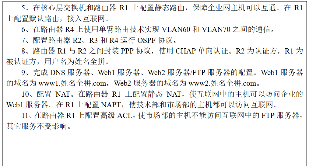
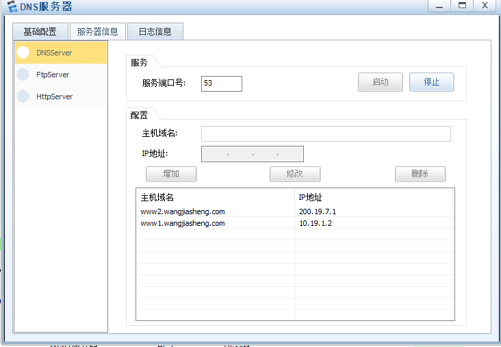
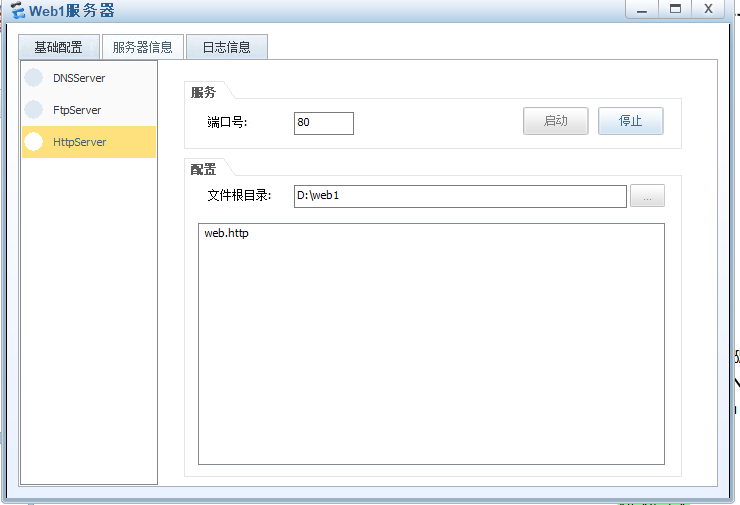
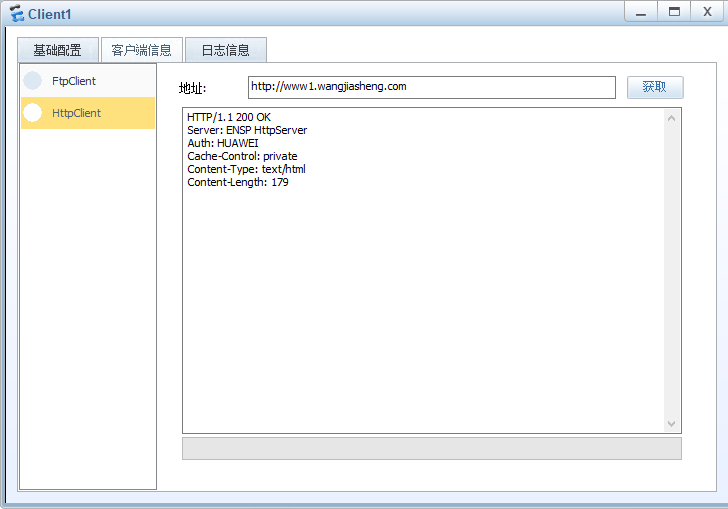
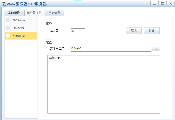
9、完成 DNS 服务器、Web1 服务器、Web2 服务器/FTP 服务器的配置。Web1 服务器的域名为 www1.姓名全拼.com,Web2 服务器的域名为 www2.姓名全拼.com。


10、配置 NAT。在路由器 R1 上配置静态 NAT,使互联网中的主机可以访问企业的Web1 服务器。在 R1 上配置 NAPT,使技术部和市场部的主机都可以访问互联网。
int s1/0/0
Nat static enable
nat static global 200.19.1.10 inside 10.19.1.2

nat address-group 1 200.19.1.20 200.19.1.30

acl 2000
rule permit source 10.19.2.0 0.0.0.255
rule permit source 10.19.3.0 0.0.0.255

int s1/0/0
nat outbound 2000 address-group 1
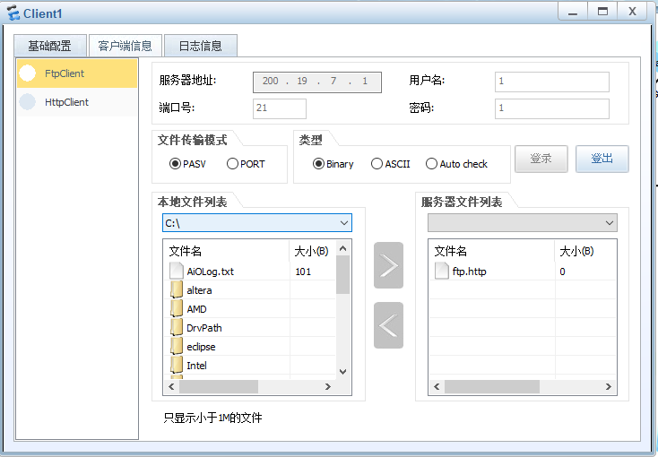
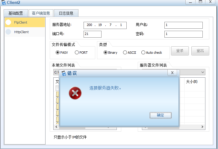
11、在路由器 R1 上配置高级 ACL,使市场部的主机不能访问互联网中的 FTP 服务器,其它服务不受影响。
[AR1]acl 3000
[AR1-acl-adv-3000]rule 10 deny tcp source 10.19.3.0 0.0.0.255 destination 200.19.7.1 0 destination-port eq 21
[AR1-acl-adv-3000]interface g0/0/0
[AR1-GigabitEthernet0/0/0]traffic-filter inbound acl 3000
[AR1-GigabitEthernet0/0/0]interface g0/0/1
[AR1-GigabitEthernet0/0/1]traffic-filter inbound acl 3000

 浙公网安备 33010602011771号