3.PIC16F877驱动LCD1602
1.LCD1602的引脚
手头上的模块是酱紫的
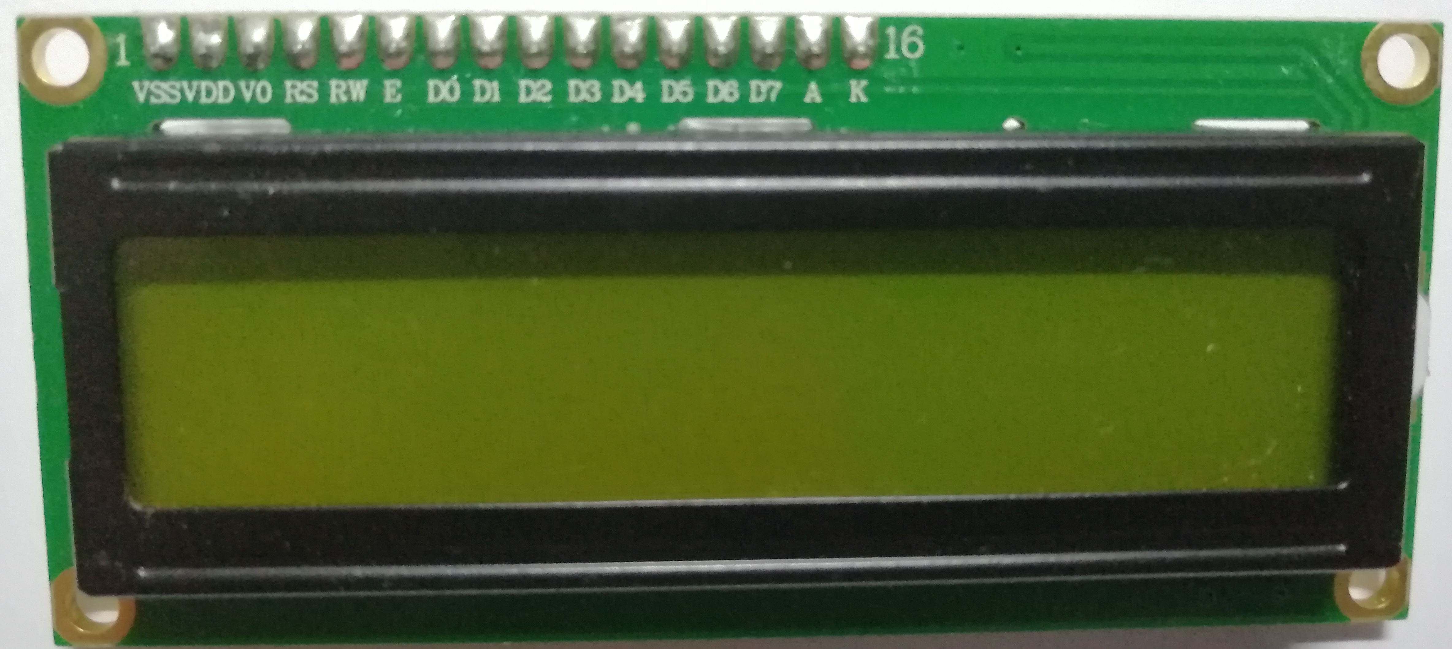
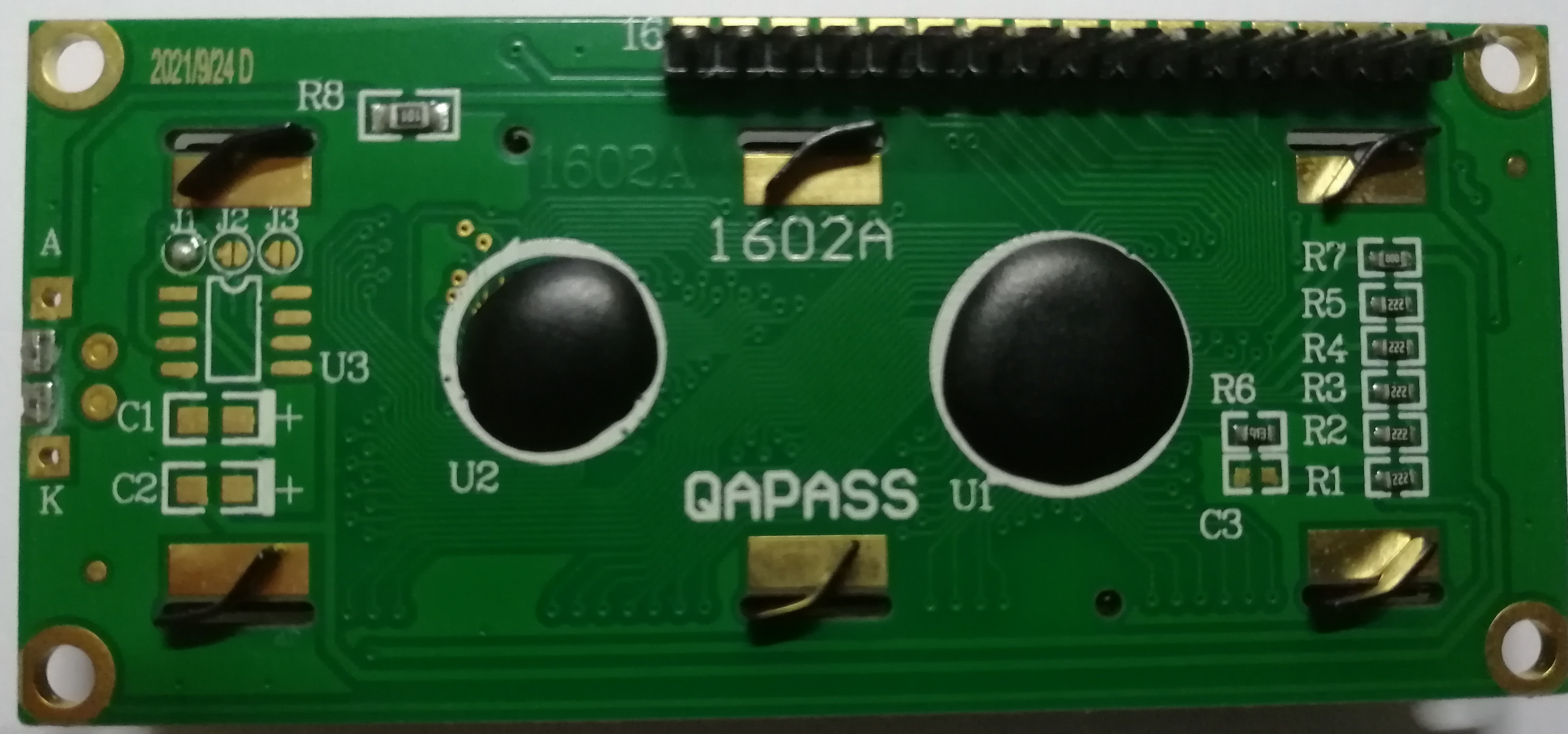
对应的头文件代码(在PIC16F877上用的)

/***********USER FUNCTIONS***********

1.    Lcd8_Init()
                - Must be called to initialise LCD.
                - Note what SFRs are effected and be sure not to overwrite these in yourt program initialisation.

2.    Lcd8_Clear()
                - Call this to Clear LCD display

3.    Lcd8_Set_Cursor(char a, char b)
                - The function sets the position of the cursor on the LCD. A = Line (1 or 2); B = Position (1 - 16).

4.    Lcd8_Write_Char(char a)
                - Write a character to the LCD e.g.     Lcd8_Write_Char('A');

5.    Lcd8_Write_String(char *a)
                - Write a string to the LCD e.g.     Lcd8_Write_Char("Hello");

6.    Lcd8_Shift_Right()
                - Shift the displayed characters one place to the right.

7.    Lcd8_Shift_Left()
                - Shift the displayed characters one place to the left.

*/


#include <xc.h>


#ifndef _XTAL_FREQ
 // Unless already defined assume 4MHz system frequency
 // This definition is required to calibrate __delay_us() and __delay_ms()
 #define _XTAL_FREQ 4000000
#endif


#define RS RE0
#define RW RE1
#define EN RE2
#define D0 RD0
#define D1 RD1
#define D2 RD2
#define D3 RD3
#define D4 RD4
#define D5 RD5
#define D6 RD6
#define D7 RD7
//LCD Functions Developed by electroSome


//LCD 8 Bit Interfacing Functions
void Lcd8_Port(char a)
{
    if(a & 1)
        D0 = 1;
    else
        D0 = 0;

    if(a & 2)
        D1 = 1;
    else
        D1 = 0;

    if(a & 4)
        D2 = 1;
    else
        D2 = 0;

    if(a & 8)
        D3 = 1;
    else
        D3 = 0;

    if(a & 16)
        D4 = 1;
    else
        D4 = 0;

    if(a & 32)
        D5 = 1;
    else
        D5 = 0;

    if(a & 64)
        D6 = 1;
    else
        D6 = 0;

    if(a & 128)
        D7 = 1;
    else
        D7 = 0;
}
void Lcd8_Cmd(char a)
{
  RS = 0;              // => RS = 0
  Lcd8_Port(a);        //Data transfer
  EN  = 1;             // => E = 1
  __delay_ms(5);
  EN  = 0;             // => E = 0
}


//=============USER FUNCTIONS=============

void Lcd8_Init()
{
      TRISE = 0x00;
      TRISD = 0x00;
      ADCON1 = 0x07;
      RE1 = 0;    //RW

    Lcd8_Port(0x00);
    RS = 0;
    __delay_ms(25);
    ///////////// Reset process from datasheet /////////
  Lcd8_Cmd(0x30);
  __delay_ms(5);
  Lcd8_Cmd(0x30);
    __delay_ms(15);
  Lcd8_Cmd(0x30);
  /////////////////////////////////////////////////////
  Lcd8_Cmd(0x38);    //function set
  Lcd8_Cmd(0x0C);    //display on,cursor off,blink off
  Lcd8_Cmd(0x01);    //clear display
  Lcd8_Cmd(0x06);    //entry mode, set increment
}


Lcd8_Clear()
{
      Lcd8_Cmd(1);
}

void Lcd8_Set_Cursor(char a, char b)
{
    if(a == 1)
      Lcd8_Cmd(0x80 + b);
    else if(a == 2)
        Lcd8_Cmd(0xC0 + b);
}


void Lcd8_Write_Char(char a)
{
   RS = 1;             // => RS = 1
   Lcd8_Port(a);             //Data transfer
   EN  = 1;             // => E = 1
  __delay_ms(4);
   EN  = 0;             // => E = 04
}

void Lcd8_Write_String(char *a)
{
    int i;
    for(i=0;a[i]!='\0';i++)
     Lcd8_Write_Char(a[i]);
}

void Lcd8_Shift_Right()
{
    Lcd8_Cmd(0x1C);
}

void Lcd8_Shift_Left()
{
    Lcd8_Cmd(0x18);
}
//End LCD 8 Bit Interfacing Functions
描述(网上数据手册找的,不同厂家的引脚名称可能不同,大部都差不多)
| VSS | VDD | V0 | RS | RW | E | D0-D7 | A | K |
| +5V | GND |
LCD 驱动电压输入端 |
指令/数据选择信号 | 读写选择信号 | 使能信号 | 数据位 | LED+(5V) | LED-(0V) |
可以看出,这么多引脚需要控制的是RS,RW,E和D0-D7,VSS,其他的引脚 A接5v,VDD,K接地,V0串联给电位器再接上5v
2.读写指令、数据
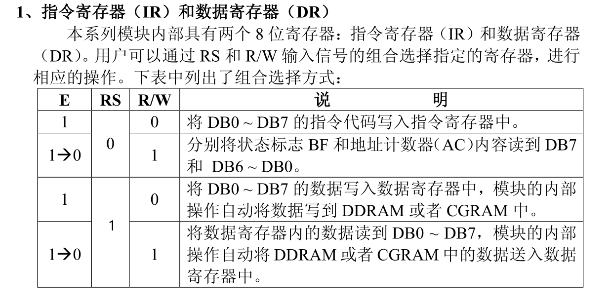
(之前网上找的一个数据手册有错,对比其他的及能用的代码才发现问题的,离谱。。。。。。)
根据LCD1602的数据手册,写指令需要先设置数据到引脚,然后设置RS=0,RW=1,E=1 -> E=0,写数据需要先设置数据到引脚,然后设置RS=0,RW=1,E=1 -> E=0
对应的写指令代码
void Lcd8_Cmd(char a)
{
  RS = 0;              // => RS = 0
  Lcd8_Port(a);        //Data transfer
  EN  = 1;             // => E = 1
  __delay_ms(5);
  EN  = 0;             // => E = 0
}
其中Lcd8_Port(a)为设置引脚的函数就是简单的把某位拿出来设置对应的口为高或低电平
void Lcd8_Port(char a)
{
    if(a & 1)
        D0 = 1;
    else
        D0 = 0;

    if(a & 2)
        D1 = 1;
    else
        D1 = 0;

    if(a & 4)
        D2 = 1;
    else
        D2 = 0;

    if(a & 8)
        D3 = 1;
    else
        D3 = 0;

    if(a & 16)
        D4 = 1;
    else
        D4 = 0;

    if(a & 32)
        D5 = 1;
    else
        D5 = 0;

    if(a & 64)
        D6 = 1;
    else
        D6 = 0;

    if(a & 128)
        D7 = 1;
    else
        D7 = 0;
}
3.初始化
头文件中的初始化是先对引脚进行配置,设置引脚为数字输出模式(手头的板子RE0-2对应RS,RW,E,RD0-7对应D0-7),然后设置写入指令(RW=0,RS=8,见上面的指令寄存器和数据寄存器的表),然后设置引脚为低电平;
void Lcd8_Init()
{
      TRISE = 0x00;
      TRISD = 0x00;
      ADCON1 = 0x07;
      RE1 = 0;    //RW

    Lcd8_Port(0x00);
    RS = 0;
    __delay_ms(25);
    ///////////// 重置 /////////
  Lcd8_Cmd(0x30);
  __delay_ms(5);
  Lcd8_Cmd(0x30);
    __delay_ms(15);
  Lcd8_Cmd(0x30);
  /////////////////////////////////////////////////////
  Lcd8_Cmd(0x38);    //Function set (功能设置)
  Lcd8_Cmd(0x0C);    //Display on/off control (显示开/关控制)
  Lcd8_Cmd(0x01);    //Clear display (清显示)
  Lcd8_Cmd(0x06);    //Entry mode set (设置输入模式)
}

重置部分传输三遍0x30(0b 0011 0000)指令,内容不重要,只是相当于重置,数据手册中建议用户最好在程序的开始进行功能设置指令的执行,
然后传输0x38(0b 0011 1000)指令,设置为8位数据总线,两行显示模式,5×7点阵+游标显示模式
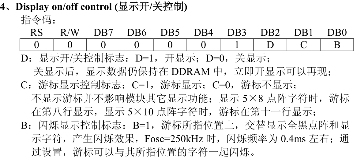
接着传输0x0C(0b 0000 1100)指令,设置开显示,游标不显示,不闪烁

再然后传输0x01指令清除显示
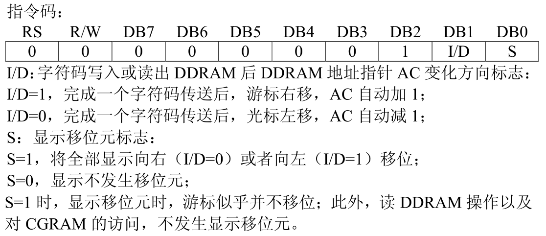
最后传输0x06(0b 0000 0110)指令设置输入模式,完成字符传送后光标自动右移动,AC自动+1,显示不发生位移元,初始化完成。
3.1ADCON1设置为0x07的原因
由于RS,RW,E都是需要数字信号,而PIC16F877A中PORTE有多种功能,可以设置为模拟引脚或者数字引脚,在数据手册(128页)中有详细提到,ADCON1配置以下寄存器

其中ADFM和ADCS2为配置ADC左右对齐和ADC时钟源,PCFG3:PCFG0为配置引脚为模拟还是数字还有ADC基准电压(参考电压),PCFG3:PCFG0的配置方法如下表
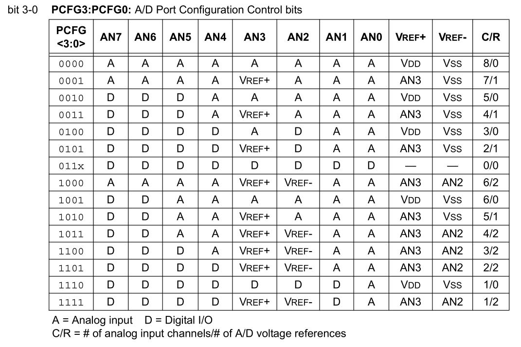

我们可以在数据手册49页或者数据手册129页得知RE0对应AN5,RE1对应AN6,RE2对应AN7,所以只要确保AN7,AN6,AN5为数字脚即可
程序中的ADCON1为0x07对应表中的(011x的x表示0和1都行),此情况PORTE全部为数字输入输出
![]()
4.写数据
写数据的代码为写单个字符和字符串,写字符串是对写单个字符重复调用,写单个字符与上文写指令相似,只是RS设置为1为写数据模式,就不再赘述
void Lcd8_Write_Char(char a)
{
   RS = 1;             // => RS = 1
   Lcd8_Port(a);             //Data transfer
   EN  = 1;             // => E = 1
  __delay_ms(4);
   EN  = 0;             // => E = 0
}

void Lcd8_Write_String(char *a)
{
    int i;
    for(i=0;a[i]!='\0';i++)
     Lcd8_Write_Char(a[i]);
}
5.移动光标
移动光标的代码为单纯的写指令
void Lcd8_Shift_Right()
{
    Lcd8_Cmd(0x1C);
}

void Lcd8_Shift_Left()
{
    Lcd8_Cmd(0x18);
}


0x1C时游标与显示一起向右移动,AC值不变,0x18时游标与显示一起向左移动,AC值不变
6、设置光标位置
设置光标也差不多是基本的写指令
void Lcd8_Set_Cursor(char a, char b)
{
    if(a == 1)
      Lcd8_Cmd(0x80 + b);
    else if(a == 2)
        Lcd8_Cmd(0xC0 + b);
}


其中AC是地址寄存器,DDRAM是显示数据寄存器,0x80即0b10000000,对应第一行的光标位置(00H),0xC0即0b11000000对应第二行光标的位置(40H 0b01000000)


 浙公网安备 33010602011771号