数字电路设计--for循环实现mux
多路选择器mux是数字电路设计中很常见的一种电路结构,平时写verilog也经常会需要用到。
但想象一个场景,输入是256bit信号,输出是8bit信号,选通信号是32bit,如果写一个组合逻辑电路,用case来描述,未免太麻烦了。
就会像这样:


1 always @(*) begin
2     dataout = 'd0;
3     case(sel)
4         32'h1: dataout = sel[31] ? datain[255-:8] : 'd0;
5         32'h2: dataout = sel[30] ? datain[246-:8] : 'd0;
6         ...
7         32'h8000: dataout = sel[0] ? datain[7-:8] : 'd0;
8     endcase
9 end
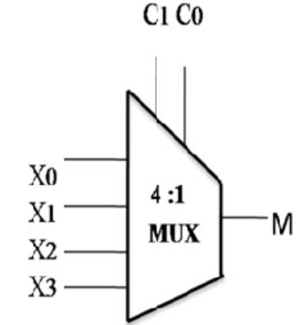
上述方式显得很冗余,因此用for循环来构造mux就更方便了,示例代码如下:(这里实现的4to1mux)
 1 module test1(input wire clk,
 2                 input wire     [15:0]     datain,
 3                 input wire     [3:0]    sel,
 4                 output    reg [3:0]    dataout);
 5
 6 integer i;
 7
 8 //always @(*) begin
 9 always @(sel) begin
10     dataout = 'd0;
11     for(i=0;i<4;i=i+1)begin:mux
12         if(sel[i])begin
13             dataout = datain[i*4+:4];
14             disable mux;
15         end
16     end
17 end
18
19 endmodule
这里我使用了disable来跳出for-loop,参考的来源中使用了break,这一用法我不太熟悉,采用modelsim仿真也会报错。
但是disable语句是可以明确跳出对应的block的,只要在begin end块中声明block name。具体可以查询IEEE规范。
简单构造一个tb看看效果,是可以实现对应功能的