m基于MATLAB的通信系统仿真,包括信号源,载波信号,放大器,带宽滤波器,接收端包括放大器,带宽滤波器,载波解调,低通滤波器等
1.算法概述
Interference : 200KHz
Signal source: 需要在给出的一个excel 文档里调用,我对应的信号是第二竖栏,就是从B1到B60
里面所有的filter(滤波器)都是自己来选值,但必须和图里要求的一样,band-pass filter 只能用带通滤波器,不可用其他代替。Low-pass filter(低通滤波器)是同样的道理。
Scaling factor为-20,
Noise为随机向量*0.3,
Interference为200khz。
这个部分主要分为放大器,带宽滤波器,载波解调,原始的信号。
2.仿真效果预览
matlab2022a仿真
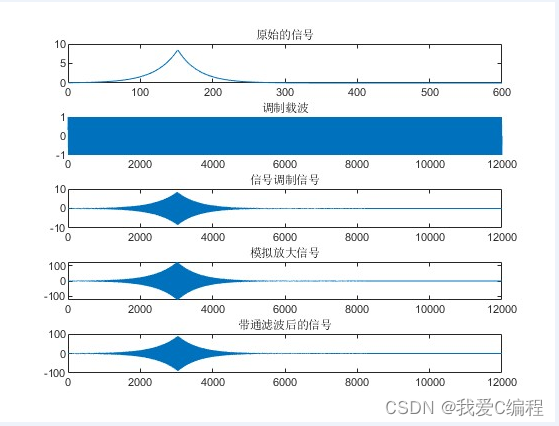
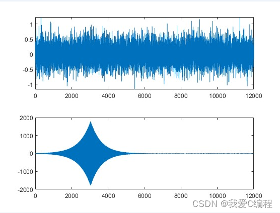
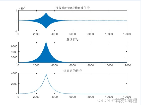

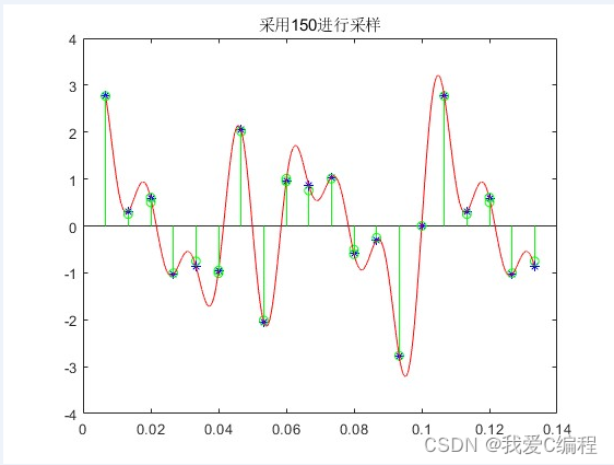
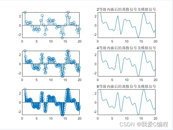
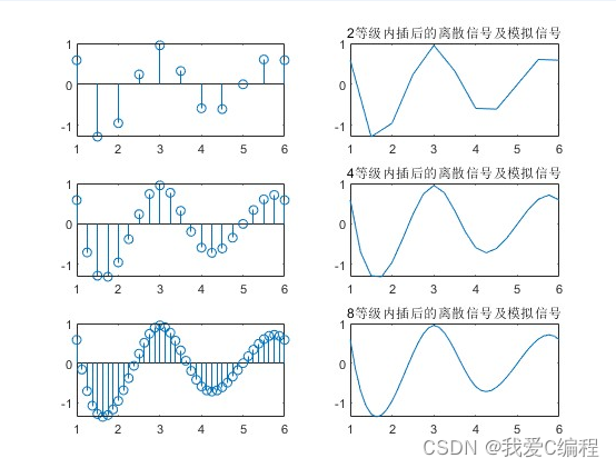
3.MATLAB部分代码预览
.................................................
%STEP1 发送端
%信号源
SINGNALS=xlsread('Signals.xls','Sheet1','B1:B600');
figure(1)
subplot(511),plot(SINGNALS),title('原始的信号');

%乘以载波
N = 20                       % Set the number of signal samples
Freq = 250000;                 % 250k
dt = 1/(N*Freq);               % Set the sample time
SimTime = 600/Freq;              % Set simulation time to 3 periods of the signal
t = dt:dt:SimTime;              % Create Time vector(from 0 upto SimTime)
Carrier= sin(2*pi*Freq*t);
subplot(512),plot(Carrier),title('调制载波');

%信号采样化
for i = 1 : length(Carrier)-1
SINGNALS1(i) = SINGNALS(floor(i/20)+1);
end
SINGNALS1(length(Carrier)) = SINGNALS1(length(Carrier)-1);

SINGNALS2=SINGNALS1.*Carrier;
% SINGNALS2=SINGNALS1.*Carrier + SINGNALS1.*Carrier.*Carrier;
subplot(513),plot(SINGNALS2),title('信号调制信号');

%放大
SINGNALS3=15*SINGNALS2;
subplot(514),plot(SINGNALS3),title('模拟放大信号');

%带通滤波器
order = 4;
wn = [0.01 0.1];
[B,A]=butter(order,wn);
SINGNALS4 = filter(B,A,SINGNALS3);
subplot(515);plot(SINGNALS4),title('带通滤波后的信号');


%STEP2 信道
figure(2)

alpha = -20;                               % scaling factor
noise = 0.3*randn(1,length(SINGNALS4));    % Generate a random number
subplot(211);plot(noise);

N2 = N;
Fre = 200000;                              % Set the frequency of the signal
dt2 = 1/(N2*Fre);                          % Set the sample time
SimTime2 = 600/Fre;                        % Set simulation time to 3 periods of the signal
t2 = dt2:dt2:SimTime2;                     % Create Time vector(from 0 upto SimTime

interference = sin(2*pi*Fre*t2);           % Determine the sinusoidal function for interference
output_sig   = SINGNALS4.* alpha;

SINGNALS5 = output_sig + noise + interference;

subplot(212);plot(SINGNALS5);

%STEP3 接收端
figure(3);
a2=6;
SINGNALS6 = a2*SINGNALS5;
order2 = 4;
wn2 = [0.01 0.1];
[B2,A2]=butter(order2,wn2);
SINGNALS7 = filter(B2,A2,SINGNALS6);
subplot(311);plot(SINGNALS7),title('接收端后的低通滤波信号');
SINGNALS8=-SINGNALS7.*Carrier;
% SINGNALS8= SINGNALS7.*Carrier;
subplot(312);plot(SINGNALS8),title('解调信号');
wn1 = 0.1;
order1 = 10; % Filter Order
[C,D] = butter(order1,wn1,'low'); % create the fourth order butterworth filter
SINGNALS9 = filter(C,D,SINGNALS8);
subplot(313);plot(SINGNALS9),title('还原后的信号');
figure(4)
subplot(211);plot(SINGNALS);title('系统发送接收信号的对比');
subplot(212);plot(SINGNALS9);axis([0,length(Carrier),0,5000]);
01-29m


