
TMS320VC5509驱动AT24C02
1. 刚开始的波形不太对,比如如下代码

        i2c_status = I2C_write( at24c02_write_buf,          //pointer to data array
                                1,                //length of data to be transmitted
                                1,                //master or slaver
                                0x78,        //slave address to transmit to
                                1,                //transfer mode of operation
                                30000            //time out for bus busy
                                );
但是实际的波形是,把0x78左移了一位,我估计是DSP5509会自动在最后一位加上读写位
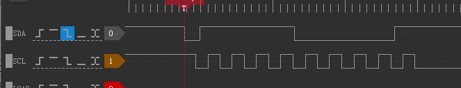
所以本次AT24C02的地址是0XA0,那么实际写的应该是0x50
        i2c_status = I2C_write( at24c02_write_buf,          //pointer to data array
                                1,                //length of data to be transmitted
                                1,                //master or slaver
                                0x50,        //slave address to transmit to
                                1,                //transfer mode of operation
                                30000            //time out for bus busy
                                );
2. 最后的综合代码如下
#include <csl.h>
#include <csl_i2c.h>
#include <stdio.h>
#include <csl_pll.h>
#include <csl_gpio.h>


#define BUF_LEN 20
#define AT24C02_WRITE_ADDR  0x50
#define AT24C02_READ_ADDR  0X50

Uint16 i2c_status;

/*锁相环的设置*/
PLL_Config  myConfig      = {
  0,    //IAI: the PLL locks using the same process that was underway
                //before the idle mode was entered
  1,    //IOB: If the PLL indicates a break in the phase lock,
                //it switches to its bypass mode and restarts the PLL phase-locking
                //sequence
  12,    //PLL multiply value; multiply 24 times
  1             //Divide by 2 PLL divide value; it can be either PLL divide value
                //(when PLL is enabled), or Bypass-mode divide value
                //(PLL in bypass mode, if PLL multiply value is set to 1)
};

/* This next struct shows how to use the I2C API */
/* Create and initialize an I2C initialization structure */
I2C_Setup I2Cinit = {
        0,              /* 7 bit address mode */
        0,         /* own address - don't care if master */
        30,            /* clkout value (Mhz)  */
        50,            /* a number between 10 and 400*/
        0,              /* number of bits/byte to be received or transmitted (8)*/
        0,              /* DLB mode on*/
        1               /* FREE mode of operation on*/
};

Uint16 at24c02_write_buf[3] ={0x00,0x00,0x00};
Uint16 test_write_buf[BUF_LEN+1] = {0};
I2C_Config testI2C;

void delay(Uint32 k)
{
   while(k--);
}


void main(void)
{
    unsigned char i= 0;
    i2c_status = 1;
    /*初始化CSL库*/
    CSL_init();

    /*设置系统的运行速度为140MHz*/
    PLL_config(&myConfig);

    /*确定方向为输出*/
    GPIO_RSET(IODIR,0xFF);
    GPIO_RSET(IODATA,0x00);

    /*I2C is undet reset*/
    I2C_RSET(I2CMDR,0);
    /*设置预分频寄存器,I2C的mode clock is 10MHz*/
    delay(100);
    I2C_RSET(I2CSAR,0x001A);
    I2C_RSET(I2CMDR,0x0620);

    I2C_setup(&I2Cinit);
    /*设置I2C的Mater clock*/
    I2C_RSET(I2CCLKL,100);
    I2C_RSET(I2CCLKH,100);

    I2C_getConfig(&testI2C);

    //
    for(i=0;i<BUF_LEN;i++)
    {
        at24c02_write_buf[0] = i;
        at24c02_write_buf[1] = 5+i;
        i2c_status = I2C_write( at24c02_write_buf,          //pointer to data array
                                2,                //length of data to be transmitted
                                1,                //master or slaver
                                AT24C02_WRITE_ADDR,        //slave address to transmit to
                                1,                //transfer mode of operation
                                30000            //time out for bus busy
                                );
        delay(100);
    }

    for(i=0;i<BUF_LEN;i++)
    {
        at24c02_write_buf[0] = i;
        at24c02_write_buf[1] = 0;
        test_write_buf[i] = 0;
        i2c_status = I2C_write( at24c02_write_buf,          //pointer to data array
                                1,                //length of data to be transmitted
                                1,                //master or slaver
                                AT24C02_WRITE_ADDR,        //slave address to transmit to
                                1,                //transfer mode of operation
                                30000            //time out for bus busy
                                );

        i2c_status = I2C_read( &(test_write_buf[i]),          //pointer to data array
                                1,                //length of data to be transmitted
                                1,                //master or slaver
                                AT24C02_READ_ADDR,        //slave address to transmit to
                                1,                //transfer mode of operation
                                30000,            //time out for bus busy
                                0
                                );
        delay(1000);
    }

    while(1);
}
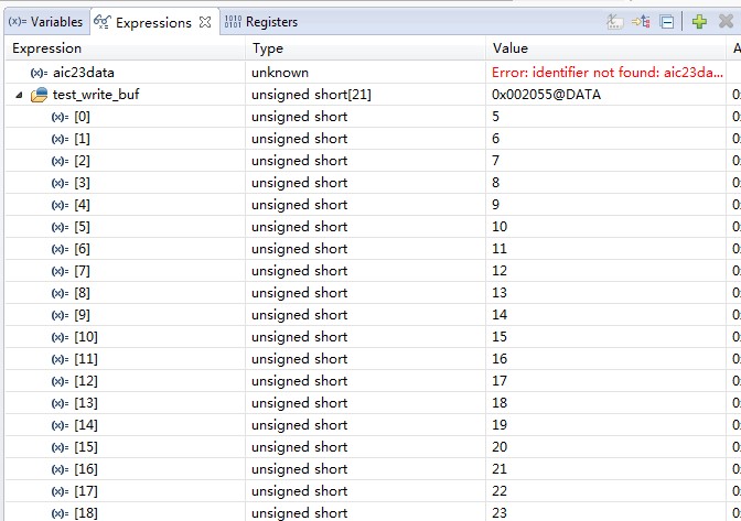
3. 看下仿真的结果
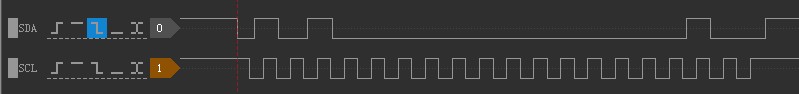
4. 看下写数据的波形

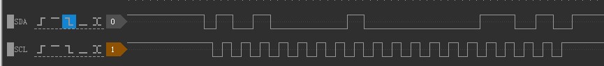
读数据的波形
分类:
DSP数字信号处理


【推荐】国内首个AI IDE,深度理解中文开发场景,立即下载体验Trae
【推荐】编程新体验,更懂你的AI,立即体验豆包MarsCode编程助手
【推荐】抖音旗下AI助手豆包,你的智能百科全书,全免费不限次数
【推荐】轻量又高性能的 SSH 工具 IShell:AI 加持,快人一步
· .NET Core 中如何实现缓存的预热?
· 从 HTTP 原因短语缺失研究 HTTP/2 和 HTTP/3 的设计差异
· AI与.NET技术实操系列:向量存储与相似性搜索在 .NET 中的实现
· 基于Microsoft.Extensions.AI核心库实现RAG应用
· Linux系列:如何用heaptrack跟踪.NET程序的非托管内存泄露
· TypeScript + Deepseek 打造卜卦网站:技术与玄学的结合
· 阿里巴巴 QwQ-32B真的超越了 DeepSeek R-1吗?
· 如何调用 DeepSeek 的自然语言处理 API 接口并集成到在线客服系统
· 【译】Visual Studio 中新的强大生产力特性
· 2025年我用 Compose 写了一个 Todo App
2018-04-12 创龙DSP6748开发板驱动LCD屏