物理引擎中的刚体转动1
在VREP中的物体上添加一个力矩看看它会怎么运动。新建一个场景,向其中添加一个立方体,将立方体抬高离开地面,并在Dynamics选项卡中将重力设置为0. 然后在立方体上施加一个力矩T={1,1,1},立方体将在力矩作用下旋转起来:


function sysCall_init()
    -- do some initialization here:

    handle=sim.getObjectHandle('Cuboid')

    graphHandle = sim.getObjectHandle('Graph')

    pos = sim.getObjectPosition(handle, -1)
    torque = {1, 1, 1}
    lineContainer = sim.addDrawingObject(sim.drawing_lines, 3, 0, -1, 99999, {0.2,0.2,0.2})
    lineDat = {pos[1],pos[2], pos[3], pos[1]+0.1*torque[1], pos[2]+0.1*torque[2], pos[3]+0.1*torque[3]}
    sim.addDrawingObjectItem(lineContainer, lineDat)
end


function sysCall_actuation()
    -- put your actuation code here
    sim.addForceAndTorque(handle,nil,torque)
end


function sysCall_sensing()
    -- put your sensing code here
    _, angularVel = sim.getVelocity(handle)
    --print(angularVel[1],angularVel[2],angularVel[3])

    sim.setGraphUserData(graphHandle,'vx',angularVel[1])
    sim.setGraphUserData(graphHandle,'vy',angularVel[2])
    sim.setGraphUserData(graphHandle,'vz',angularVel[3])
end
VREP中给物体施加力有两个函数sim.addForce和sim.addForceAndTorque. 其中sim.addForceAndTorque施加的有心力(central force:有心力的方向永远指向一个固定点或动点)作用在物体质心上,并且以世界坐标系为参照进行描述(they are expressed as absolute values, i.e. relative to the world reference frame)。而sim.addForce施加非有心力(non-central force). Note that the force is applied just for one simulation pass. If you want a specific force to be constantly present, you will have to add it again in each simulation step. Remember that simAddForceAndTorque needs to be called constantly, since the forces added like that are reset at each simulation step.
为了计算和观察方便,设立方体质量及惯性参数都为1,那么根据欧拉方程,可以算出物体沿三个坐标分量(以世界坐标系为参考)的角加速度值都应该为1rad/s2

VREP中获取物体的速度和角速度也有两个函数,分别是sim.getVelocity (return the velocity computed by the physics engine. works only with dynamically simulated shape) 以及sim.getObjectVelocity(returns a velocity computed by V-REP. works with all scene objects)
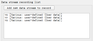
代码中使用sim.getVelocity函数获取物体角速度分量后,通过Graph自定义数据(User data)的方式在图表上绘制出来。可以看出三个方向的角速度曲线重合,并且斜率均为1

物理引擎中已知作用在物体上的力和力矩,计算物体的运动需要用到牛顿运动定律。对于平动,定义逆质量(inverse mass )将牛顿第二运动定律改写为:
对于转动,定义逆惯性张量(inverse inertia tensor ),根据动量矩定力:
求出加速度和角加速度后对其进行积分可得到速度、角速度,进一步积分可得位置和姿态。在Bullet2.78中该过程的实现如下。注意程序中会对角速度进行限制,因为如果角速度过大在碰撞检测时可能检测不到碰撞,导致物体间发生穿透。

void btRigidBody::integrateVelocities(btScalar step)
{
    if (isStaticOrKinematicObject())
        return;

    m_linearVelocity += m_totalForce * (m_inverseMass * step);
    m_angularVelocity += m_invInertiaTensorWorld * m_totalTorque * step;

#define MAX_ANGVEL SIMD_HALF_PI
    /// clamp angular velocity. collision calculations will fail on higher angular velocities
    btScalar angvel = m_angularVelocity.length();
    if (angvel*step > MAX_ANGVEL)
    {
        m_angularVelocity *= (MAX_ANGVEL/step) /angvel;
    }

}
下图可以明显看出角速度增大到一定幅度后被限制在一个最大值上。

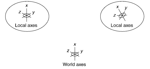
对于转动,这里有一个问题:上面的方程力矩、角加速度 、以及惯性张量都是定义在世界坐标系中的。如果动坐标系(Local axes)的姿态与世界坐标系不一致,那么世界坐标系中描述的惯性张量将随着物体的姿态不同实时变化。为了能应用上面的方程,需要将动坐标系中的惯性张量转换到世界坐标系下来表达。

下面进行简单的推导(参考3D Rigid Body Dynamics: The Inertia Tensor),假设世界坐标系下刚体的动量矩矢量为,动坐标系下的动量矩矢量为,动坐标系到世界坐标系的转换矩阵为。那么:
因为旋转矩阵R为正交对称矩阵,所以有,是单位矩阵。因此,将惯性张量从局部坐标系转换到世界坐标系下的变换为:
对于旋转矩阵则,
Bullet物理引擎中计算世界坐标系下物体逆惯性张量矩阵的函数如下。可以看出局部坐标系下的逆惯性张量矩阵在设置物体质量属性的时候就已经计算好了,局部坐标系一般为物体的惯性主轴坐标系,该坐标系下惯性张量矩阵只有主对角线上有元素,计算其逆矩阵只需对主对角线元素求倒数。
void btRigidBody::setMassProps(btScalar mass, const btVector3& inertia)
{
    //...
    //...
    m_invInertiaLocal.setValue(inertia.x() != btScalar(0.0) ? btScalar(1.0) / inertia.x(): btScalar(0.0),
    inertia.y() != btScalar(0.0) ? btScalar(1.0) / inertia.y(): btScalar(0.0),
    inertia.z() != btScalar(0.0) ? btScalar(1.0) / inertia.z(): btScalar(0.0));
    //...
}


void btRigidBody::updateInertiaTensor()
{
    m_invInertiaTensorWorld = m_worldTransform.getBasis().scaled(m_invInertiaLocal) * m_worldTransform.getBasis().transpose();
}
另外出现了一个新的问题,我们将角加速度积分得到世界坐标系下描述的角速度后怎么样将其表示成物体姿态?(We need to update the orientation by the angular velocity)因为后面计算旋转矩阵R需要知道物体当前姿态,否则迭代就没法进行。

在计算机图形学和刚体旋转的研究中经常用四元数来表示物体的姿态。下面的公式将绝对坐标系下的角速度与四元数的微分联系起来(证明可以参考Quaternion Calculus以及Quaternion and Rotation):
其中,为代表物体姿态随时间变化的四元数,W为角速度构造出的实部为零的四元数:,“*”表示四元数乘法。
这一公式简单的证明过程如下:
在时刻,物体姿态可由四元数表示。在时间段内物体绕着瞬时轴从运动到,这一时间段内的角位移为。根据四元数与Axis-Angle之间的关系可知:
在时间段内姿态的变换也可以通过四元数乘法(与旋转矩阵乘法意义类似)得到:
现在我们开始推导:
上面式子中第一项是关于的高阶无穷小,因此Δt→0时为零。所以有:
上面公式写成离散形式如下:
根据这一公式可以用角速度更新物体的姿态,具体的实现可以参考cyclone-physics物理引擎(与Game Physics Engine Development一书相配套)源代码中core.h头文件的第592行:

class Quaternion
    {
    public:
        union {
            struct {
                /**
                 * Holds the real component of the quaternion.
                 */
                real r;

                /**
                 * Holds the first complex component of the
                 * quaternion.
                 */
                real i;

                /**
                 * Holds the second complex component of the
                 * quaternion.
                 */
                real j;

                /**
                 * Holds the third complex component of the
                 * quaternion.
                 */
                real k;
            };

            /**
             * Holds the quaternion data in array form.
             */
            real data[4];
        };

        // ... other Quaternion code as before ...

        /**
         * The default constructor creates a quaternion representing
         * a zero rotation.
         */
        Quaternion() : r(1), i(0), j(0), k(0) {}

        /**
         * The explicit constructor creates a quaternion with the given
         * components.
         *
         * @param r The real component of the rigid body's orientation
         * quaternion.
         *
         * @param i The first complex component of the rigid body's
         * orientation quaternion.
         *
         * @param j The second complex component of the rigid body's
         * orientation quaternion.
         *
         * @param k The third complex component of the rigid body's
         * orientation quaternion.
         *
         * @note The given orientation does not need to be normalised,
         * and can be zero. This function will not alter the given
         * values, or normalise the quaternion. To normalise the
         * quaternion (and make a zero quaternion a legal rotation),
         * use the normalise function.
         *
         * @see normalise
         */
        Quaternion(const real r, const real i, const real j, const real k)
            : r(r), i(i), j(j), k(k)
        {
        }

        /**
         * Normalises the quaternion to unit length, making it a valid
         * orientation quaternion.
         */
        void normalise()
        {
            real d = r*r+i*i+j*j+k*k;

            // Check for zero length quaternion, and use the no-rotation
            // quaternion in that case.
            if (d < real_epsilon) {
                r = 1;
                return;
            }

            d = ((real)1.0)/real_sqrt(d);
            r *= d;
            i *= d;
            j *= d;
            k *= d;
        }

        /**
         * Multiplies the quaternion by the given quaternion.
         *
         * @param multiplier The quaternion by which to multiply.
         */
        void operator *=(const Quaternion &multiplier)
        {
            Quaternion q = *this;
            r = q.r*multiplier.r - q.i*multiplier.i -
                q.j*multiplier.j - q.k*multiplier.k;
            i = q.r*multiplier.i + q.i*multiplier.r +
                q.j*multiplier.k - q.k*multiplier.j;
            j = q.r*multiplier.j + q.j*multiplier.r +
                q.k*multiplier.i - q.i*multiplier.k;
            k = q.r*multiplier.k + q.k*multiplier.r +
                q.i*multiplier.j - q.j*multiplier.i;
        }

        /**
         * Adds the given vector to this, scaled by the given amount.
         * This is used to update the orientation quaternion by a rotation
         * and time.
         *
         * @param vector The vector to add.
         *
         * @param scale The amount of the vector to add.
         */
        void addScaledVector(const Vector3& vector, real scale)
        {
            Quaternion q(0,
                vector.x * scale,
                vector.y * scale,
                vector.z * scale);
            q *= *this;
            r += q.r * ((real)0.5);
            i += q.i * ((real)0.5);
            j += q.j * ((real)0.5);
            k += q.k * ((real)0.5);
        }

        void rotateByVector(const Vector3& vector)
        {
            Quaternion q(0, vector.x, vector.y, vector.z);
            (*this) *= q;
        }
    };
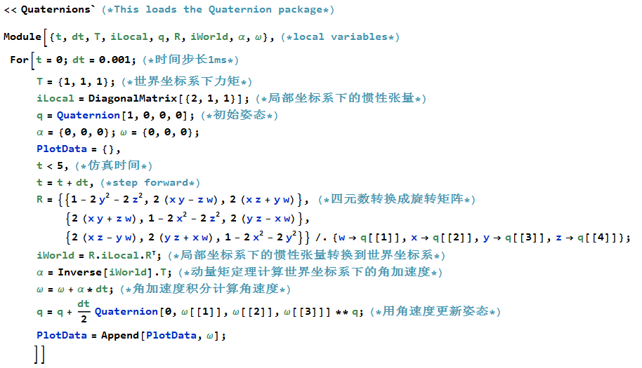
将上面公式结合起来,用Mathematica编程计算物体在力矩下的运动。仿真5秒,时间步长为1毫秒:

绘制出世界坐标系下的角速度曲线如下:

在VREP中选bullet2.78或Newton物理引擎进行仿真,结果与上面的计算一致:

但是当选择bullet2.83或ODE物理引擎时计算结果与上面的不同:

用ADAMS、SIMPACK等更精确的动力学仿真软件进行模拟,得到的结果也与bullet2.83一致。对下面同样的代码,bullet2.78(2.82)和bullet2.83给出的结果完全不同,实际上bullet2.83的结果是更准确的。在某些游戏物理引擎中,为了保证计算的实时性或稳定性对物理过程进行了一定的简化,省去了实际动量矩定理公式中的某些复杂的项。

#include <btBulletDynamicsCommon.h>
#include <stdio.h>
#include <iostream>
#include <fstream>
using namespace std;

/// This is a Hello World program for running a basic Bullet physics simulation

int main(int argc, char** argv)
{

    btBroadphaseInterface* broadphase = new btDbvtBroadphase();

    ///collision configuration contains default setup for memory, collision setup. Advanced users can create their own configuration.
    btDefaultCollisionConfiguration* collisionConfiguration = new btDefaultCollisionConfiguration();

    ///use the default collision dispatcher. For parallel processing you can use a differnt dispatcher
    btCollisionDispatcher* dispatcher = new btCollisionDispatcher(collisionConfiguration);

    ///the default constraint solver. For parallel processing you can use a different solver
    btSequentialImpulseConstraintSolver* solver = new btSequentialImpulseConstraintSolver;

    ///instantiate the dynamics world
    btDiscreteDynamicsWorld* dynamicsWorld = new btDiscreteDynamicsWorld(dispatcher, broadphase, solver, collisionConfiguration);

    ///sets the gravity
    dynamicsWorld->setGravity(btVector3(0, 0, 0));


    btCollisionShape* Shape = new btSphereShape(1);


    //The btTransform class supports rigid transforms with only translation and rotation
    btDefaultMotionState* MotionState = new btDefaultMotionState(btTransform(btQuaternion(0, 0, 0, 1), btVector3(0, 50, 0)));

    btScalar mass = 1;
    btVector3 Inertia(2, 1, 1);
    btVector3 torque(1, 1, 1);
    btVector3 angularVelocity(0, 0, 0);

    ///when bodies are constructed, they are passed certain parameters. This is done through a special structure Bullet provides for this.
    ///rigid body is dynamic if and only if mass is non zero, otherwise static
    btRigidBody::btRigidBodyConstructionInfo RigidBodyCI(mass, MotionState, Shape, Inertia);
    btRigidBody* RigidBody = new btRigidBody(RigidBodyCI);
    dynamicsWorld->addRigidBody(RigidBody);

    ofstream outfile("data.csv", ios::out);
    for (int i = 0; i < 300; i++) {

        RigidBody->applyTorque(torque);

        dynamicsWorld->stepSimulation(1 / 60.f, 10);

        angularVelocity = RigidBody->getAngularVelocity();

        outfile << angularVelocity.getX() << "," << angularVelocity.getY() << "," << angularVelocity.getZ() << endl;
    }

    outfile.close();

    delete Shape;


    delete dynamicsWorld;
    delete solver;
    delete dispatcher;
    delete collisionConfiguration;
    delete broadphase;

    printf("Press a key to exit\n");
    getchar();
}
接下来我们将进行正确的公式推导和转动模拟。
参考:
Modern Robotics Mechanics, Planning, and Control Chapter 8. Dynamics of Open Chains
Game Physics Engine Development(https://github.com/idmillington/cyclone-physics)
Overview of core principles behind real-time physics systems


【推荐】国内首个AI IDE,深度理解中文开发场景,立即下载体验Trae
【推荐】编程新体验,更懂你的AI,立即体验豆包MarsCode编程助手
【推荐】抖音旗下AI助手豆包,你的智能百科全书,全免费不限次数
【推荐】轻量又高性能的 SSH 工具 IShell:AI 加持,快人一步
· AI与.NET技术实操系列:向量存储与相似性搜索在 .NET 中的实现
· 基于Microsoft.Extensions.AI核心库实现RAG应用
· Linux系列:如何用heaptrack跟踪.NET程序的非托管内存泄露
· 开发者必知的日志记录最佳实践
· SQL Server 2025 AI相关能力初探
· 震惊!C++程序真的从main开始吗?99%的程序员都答错了
· 【硬核科普】Trae如何「偷看」你的代码?零基础破解AI编程运行原理
· 单元测试从入门到精通
· 上周热点回顾(3.3-3.9)
· winform 绘制太阳,地球,月球 运作规律