V-rep学习笔记:Reflexxes Motion Library 1
V-REP中集成了在线运动轨迹生成库Reflexxes Motion Library Type IV,目前Reflexxes公司已经被谷歌收购。(The Reflexxes Motion Libraries provide instantaneous trajectory generation capabilities for motion control systems. Reflexxes Motion Library contains a set of On-Line Trajectory Generation (OTG) algorithms that are designed to control robots and mechanical systems.) Reflexxes的众多优点使其可以应用于机器人、数控机床和伺服驱动系统等领域。

随着计算机技术的发展,数控系统已经从最初的由数字逻辑电路构成的硬线数控系统发展到了以计算机为核心的计算机数控(Computer Numerical Control,CNC)系统。相对于硬线数控系统而言,CNC系统的控制功能主要由软件实现,并可处理逻辑电路难以处理的复杂信息,因而具有较高的柔性和更高的性能。高速加工对CNC的最基本要求:以足够快的速度处理数据、为各进给轴加减速产生无冲击的理论值。高速加工CNC的核心技术是样条实时插补和无冲击的加速器。如果jerk(加加速读/突变)过大,可在短时间内实现加速,但同时会造成机床的振动,从而使所加工表面出现条纹,降低了表面质量。如果加加速过小,可以实现高的表面质量,但很难实现快加速功能。因此,为了保证在高速情况下加工出高质量表面,合理的机床加加速非常重要。

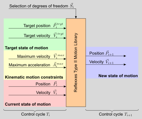
在基于位置的在线轨迹生成算法中输入、输出如下图所示。输入端:当前状态包括当前位置/姿态向量以及当前速度向量;运动约束包括最大速度和最大加速度(在Type IV库中还可以支持加加速度);目标状态包括目标位置/姿态以及目标速度。为了保证算法的可行性和数值稳定性,输入参数需要满足以下几点要求:
(1)最大速度和最大加速度必须大于0;
(2)在位置模式下(for the position-based algorithm),最大速度必须大于或等于目标速度;
(3)所有输入参数的数值必须在一定的范围内。 For the position-based algorithm this is range is specified by

and for the velocity-based algorithm


Input and output values of the position-based Type II On-Line Trajectory Generation algorithm of the Reflexxes Motion Libraries
提供合理的输入参数后,可以从输出端获取数据,用于底层控制。下面是一个生成三自由度关节轨迹的简单例子。The position-based On-Line Trajectory Generation algorithm of the Type II Reflexxes Motion Library is called by the method ReflexxesAPI::RMLPosition(). In this example (cf. Example 1 — Introduction to the Position-based algorithm), we assume to control a simple Cartesian robot with three translational degrees of freedom, and we apply the following input values at time instant  .
.
三个轴的输入参数如下:

下载Reflexxes Motion Libraries Type II后将其解压,用Visual Studio打开工程文件生成TypeIIRML.lib(参考Download and Build Instructions for the Type II Reflexxes Motion Library)。将01_RMLPositionSampleApplication中的源文件代码进行修改,添加写文件操作,将生成的输出数据记录在文本文件中:

#include <stdio.h>
#include <stdlib.h>
#include <fstream>
#include <iostream>

#include <ReflexxesAPI.h>
#include <RMLPositionFlags.h>
#include <RMLPositionInputParameters.h>
#include <RMLPositionOutputParameters.h>


//*************************************************************************
// defines

#define CYCLE_TIME_IN_SECONDS                   0.001    //one millisecond
#define NUMBER_OF_DOFS                          3


int main()
{
    // ********************************************************************
    // Variable declarations and definitions

    int                         ResultValue = 0;

    ReflexxesAPI                *RML = NULL;

    RMLPositionInputParameters  *IP = NULL;

    RMLPositionOutputParameters *OP = NULL;

    RMLPositionFlags            Flags;

    // ********************************************************************
    // Creating all relevant objects of the Type II Reflexxes Motion Library

    RML = new ReflexxesAPI(NUMBER_OF_DOFS, CYCLE_TIME_IN_SECONDS);

    IP = new RMLPositionInputParameters(NUMBER_OF_DOFS);

    OP = new RMLPositionOutputParameters(NUMBER_OF_DOFS);


    // ********************************************************************
    // Set-up the input parameters

    // In this test program, arbitrary values are chosen. If executed on a
    // real robot or mechanical system, the position is read and stored in
    // an RMLPositionInputParameters::CurrentPositionVector vector object.
    // For the very first motion after starting the controller, velocities
    // and acceleration are commonly set to zero. The desired target state
    // of motion and the motion constraints depend on the robot and the
    // current task/application.
    // The internal data structures make use of native C data types
    // (e.g., IP->CurrentPositionVector->VecData is a pointer to
    // an array of NUMBER_OF_DOFS double values), such that the Reflexxes
    // Library can be used in a universal way.

    IP->CurrentPositionVector->VecData[0] = 100.0;
    IP->CurrentPositionVector->VecData[1] = 0.0;
    IP->CurrentPositionVector->VecData[2] = 50.0;

    IP->CurrentVelocityVector->VecData[0] = 100.0;
    IP->CurrentVelocityVector->VecData[1] = -220.0;
    IP->CurrentVelocityVector->VecData[2] = -50.0;

    IP->CurrentAccelerationVector->VecData[0] = -150.0;
    IP->CurrentAccelerationVector->VecData[1] = 250.0;
    IP->CurrentAccelerationVector->VecData[2] = -50.0;

    IP->MaxVelocityVector->VecData[0] = 300.0;
    IP->MaxVelocityVector->VecData[1] = 100.0;
    IP->MaxVelocityVector->VecData[2] = 300.0;

    IP->MaxAccelerationVector->VecData[0] = 300.0;
    IP->MaxAccelerationVector->VecData[1] = 200.0;
    IP->MaxAccelerationVector->VecData[2] = 100.0;

    IP->TargetPositionVector->VecData[0] = -600.0;
    IP->TargetPositionVector->VecData[1] = -200.0;
    IP->TargetPositionVector->VecData[2] = -350.0;

    IP->TargetVelocityVector->VecData[0] = 50.0;
    IP->TargetVelocityVector->VecData[1] = -50.0;
    IP->TargetVelocityVector->VecData[2] = -200.0;

    IP->SelectionVector->VecData[0] = true;
    IP->SelectionVector->VecData[1] = true;
    IP->SelectionVector->VecData[2] = true;

    std::ofstream out("out.txt", std::ios::app);
    // ********************************************************************
    // Starting the control loop

    while (ResultValue != ReflexxesAPI::RML_FINAL_STATE_REACHED)
    {
        // Calling the Reflexxes OTG algorithm
        ResultValue = RML->RMLPosition(*IP, OP, Flags);

        if (ResultValue < 0)
        {
            printf("An error occurred (%d).\n", ResultValue);
            break;
        }

        // ****************************************************************
        // Here, the new state of motion, that is
        //
        // - OP->NewPositionVector
        // - OP->NewVelocityVector
        // - OP->NewAccelerationVector
        //
        // can be used as input values for lower level controllers. In the
        // most simple case, a position controller in actuator space is
        // used, but the computed state can be applied to many other
        // controllers (e.g., Cartesian impedance controllers,
        // operational space controllers).
        // ****************************************************************
        for (int i = 0; i < 3; i++)
            out << OP->NewPositionVector->VecData[i] << ",";
        out << std::endl;
        // ****************************************************************
        // Feed the output values of the current control cycle back to
        // input values of the next control cycle

        *IP->CurrentPositionVector = *OP->NewPositionVector;
        *IP->CurrentVelocityVector = *OP->NewVelocityVector;
        *IP->CurrentAccelerationVector = *OP->NewAccelerationVector;
    }

    // ********************************************************************
    // Deleting the objects of the Reflexxes Motion Library end terminating
    // the process

    delete  RML;
    delete  IP;
    delete  OP;

    out.close();

    exit(EXIT_SUCCESS);
}
while循环中调用RMLPosition函数(This is the central method of each Reflexxes Type Motion Library)单步执行轨迹生成算法。如果还没达到目标状态,该函数返回ReflexxesAPI::RML_WORKING;如果已达到设定的运动状态则返回ReflexxesAPI::RML_FINAL_STATE_REACHED,其它返回值可以参见API手册。
将记录的三个轴的位置数据在Excel中用折线图显示出来(速度和加速度信息也可以按照同样方式操作):

可以看出达到设定的目标位置。Reflexxes Motion Library有更复杂和强大的用法,这里只是先作一个简单的介绍。
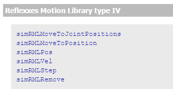
在V-REP中集成了Reflexxes Motion Library type IV C++库,目前在lua API中有如下几个函数可以使用:

将UR5机器人从模型库拖到新建的场景里中,与其关联的代码里设置了当前关节速度、加速度以及运动过程中的最大速度、加速度、目标速度以及目标位置。然后调用simRMLMoveToJointPositions同时移动UR机器人的6个关节使其按照运动规律达到目标位置。

-- This is a threaded script, and is just an example!

jointHandles={-1,-1,-1,-1,-1,-1}
for i=1,6,1 do
    jointHandles[i]=simGetObjectHandle('UR5_joint'..i)
end

-- Set-up some of the RML vectors:
vel=180
accel=40
jerk=80
currentVel={0,0,0,0,0,0,0}
currentAccel={0,0,0,0,0,0,0}
maxVel={vel*math.pi/180,vel*math.pi/180,vel*math.pi/180,vel*math.pi/180,vel*math.pi/180,vel*math.pi/180}
maxAccel={accel*math.pi/180,accel*math.pi/180,accel*math.pi/180,accel*math.pi/180,accel*math.pi/180,accel*math.pi/180}
maxJerk={jerk*math.pi/180,jerk*math.pi/180,jerk*math.pi/180,jerk*math.pi/180,jerk*math.pi/180,jerk*math.pi/180}
targetVel={0,0,0,0,0,0}

targetPos1={90*math.pi/180,90*math.pi/180,-90*math.pi/180,90*math.pi/180,90*math.pi/180,90*math.pi/180}

-- simRMLMoveToJointPositions: Moves (actuates) several joints at the same time using the Reflexxes Motion Library.
-- This function can only be called from child scripts running in a thread
--[[
number result,table newPos,table newVel,table newAccel,number timeLeft=simRMLMoveToJointPositions(table jointHandles,
                                                       number flags,table currentVel,table currentAccel,table maxVel,
                                           table maxAccel,table maxJerk,table targetPos,table targetVel,table direction)
--]]
simRMLMoveToJointPositions(jointHandles,-1,currentVel,currentAccel,maxVel,maxAccel,maxJerk,targetPos1,targetVel)

targetPos2={-90*math.pi/180,45*math.pi/180,90*math.pi/180,135*math.pi/180,90*math.pi/180,90*math.pi/180}
simRMLMoveToJointPositions(jointHandles,-1,currentVel,currentAccel,maxVel,maxAccel,maxJerk,targetPos2,targetVel)

targetPos3={0,0,0,0,0,0}
simRMLMoveToJointPositions(jointHandles,-1,currentVel,currentAccel,maxVel,maxAccel,maxJerk,targetPos3,targetVel)
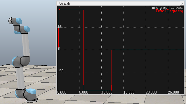
添加一个Graph记录基座转动关节的角位移,可以看出确实符合程序中的设置:0°→90°→-90°→0°

参考:


【推荐】国内首个AI IDE,深度理解中文开发场景,立即下载体验Trae
【推荐】编程新体验,更懂你的AI,立即体验豆包MarsCode编程助手
【推荐】抖音旗下AI助手豆包,你的智能百科全书,全免费不限次数
【推荐】轻量又高性能的 SSH 工具 IShell:AI 加持,快人一步
· AI与.NET技术实操系列:向量存储与相似性搜索在 .NET 中的实现
· 基于Microsoft.Extensions.AI核心库实现RAG应用
· Linux系列:如何用heaptrack跟踪.NET程序的非托管内存泄露
· 开发者必知的日志记录最佳实践
· SQL Server 2025 AI相关能力初探
· 震惊!C++程序真的从main开始吗?99%的程序员都答错了
· 【硬核科普】Trae如何「偷看」你的代码?零基础破解AI编程运行原理
· 单元测试从入门到精通
· 上周热点回顾(3.3-3.9)
· winform 绘制太阳,地球,月球 运作规律