[ZigBee] 10、ZigBee之睡眠定时器
0、概述
睡眠定时器用于设置系统进入和退出低功耗睡眠模式之间的周期。睡眠定时器还用于当进入低功耗睡眠模式时,维持定时器2 的定时。
睡眠定时器的主要功能如下:
● 24 位的定时器正计数器,运行在32kHz 的时钟频率
● 24 位的比较器,具有中断和DMA 触发功能
● 24 位捕获
1、概述
睡眠定时器是一个24 位的定时器,运行在一个32kHz 的时钟频率(可以是RCOSC 或XOSC)上。定时器在复位之后立即启动,如果没有中断就继续运行。定时器的当前值可以从SFR 寄存器ST2:ST1:ST0 中读取。
2、定时器比较
一次定时器比较发生在定时器的值等于24位比较器的值,寄存器ST2:ST1:ST0可以用来设置比较器的值。 当STLOAD.LDRDY=1写入ST0发起加载新的比较值。当STLOAD.LDRDY=0软件不能开始一个新的加载,直到它为1。
Reading ST0 captures(捕获) the current value of the 24-bit counter. Thus, the ST0 register must be read before ST1 and ST2 to capture a correct Sleep Timer count value.
When a timer compare occurs the interrupt flag STIF is asserted.
The current timer value is updated each time a positive clock edge on the 32 kHz clock is detected by the system clock. Thus, when returning from PM1/2/3 (where the system clock is shut down) the Sleep Timer value in ST2:ST1:ST0 is not up-to-date if a positive edge on the 32 kHz clock has not been detected yet. To ensure an updated value is read, wait for a positive transition on the 32 kHz clock by polling(轮询) the SLEEPSTA.CLK32K bit, before reading the Sleep Timer value.
The interrupt enable bit for the ST interrupt is IEN0.STIE, and the interrupt flag is IRCON.STIF.
当运行在除了PM3之外的所有供电模式,睡眠定时器才会运行。因此,睡眠定时器的值在PM3模式下不保存。在PM1和PM2模式下,睡眠定时器捕获事件用来唤醒设备到active模式进行active操作。The default value of the compare value after reset is 0xFF FFFF。
The Sleep Timer compare can also be used as a DMA trigger, here I don't want to talk about.
Note that: if supply voltage drops below 2 V while in PM2, 睡眠间隔 might be affected.
3、定时器捕获
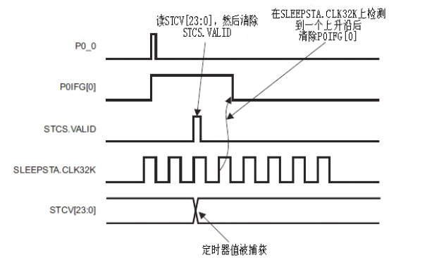
当设置了已选I/O 引脚的中断标志,且32 kHz 时钟检测到这一事件时,发生定时器捕获。 Sleep Timer capture is enabled by setting STCC.PORT[1:0] and STCC.PIN[2:0] to the I/O pin that is to be used to trigger the capture. When STCS.VALID goes high, the capture value in STCV2:STCV1:STCV0 can be read.
捕获值多于在I/O 引脚上的事件瞬间的值,因此如果时序需要,软件必须从捕获的值中间减去一个。要使能一个新的捕获,遵循以下步骤:
1. 清除STCS.VALID。
2. 等待直到SLEEPSTA.CLK32K 变为低电平。
3. 等待直到SLEEPSTA.CLK32K 变为高电平。
4. 清除P0IFG/P1IFG/P2IFG 寄存器中的引脚中断标志。
This sequence, using rising edge on P0.0 as an example, is shown in following:

It is not possible to switch input capture pin while capture is enabled. Capture must be disabled before a new input capture pin can be selected. To disable capture follow these steps (if disabling interrupts for up to half a 32 kHz cycle (~15.26 ms) is OK):
1. Disable interrupts
2. Wait until SLEEPSTA.CLK32K is high.
3. Set STCC.PORT[1:0] to 3. This disables capture.
4、睡眠定时器寄存器
睡眠定时器使用的寄存器是:
• ST2 – 睡眠定时器2
• ST1 – 睡眠定时器1
• ST0 – 睡眠定时器0
· STLOAD – 睡眠定时器加载状态
· STCC – 睡眠定时器捕获控制
· STCS – 睡眠定时器捕获状态
· STCV0 – 睡眠定时器捕获值字节0
· STCV1 – 睡眠定时器捕获值字节1
· STCV2 – 睡眠定时器捕获值字节2
5、DEMO PROJECT——系统睡眠中断唤醒
Zigbee的特点是远距离低功耗的无线传输设备,节点模块闲时可以进入睡眠模式,在需要传输数据时候进行唤醒,能进一步节省电量。
系统电源有以下几种管理模式:
- * 全功能模式:高频晶振(16M或者32M)和低频晶振(32.768K RCOSC/XOSC)全部工作,数字处理器模块正常工作;
* PM1:高频晶振关闭,低频晶振正常工作,数字核心模块正常工作;
* PM2:低频晶振工作,数字核心模块关闭,系统通过RESET,外部中断或者睡眠计数器溢出唤醒;
* PM3:晶振全部关闭,数字处理器核心模块关闭,系统只能通过RESET或者外部中断唤醒,此模式功耗最低;
本工程实现的功能是:将睡眠模式下的CC2530通过安检中断唤醒,观察LED闪烁现象。
代码:
  1 /****************************************************************************
  2 * 文 件 名: main.c
  3 * 描    述: LED1闪烁3次后进入睡眠状态,通过按下按键S1产生外部中断进行唤醒
  4 ****************************************************************************/
  5 #include <ioCC2530.h>
  6
  7 typedef unsigned char uchar;
  8 typedef unsigned int  uint;
  9
 10 #define LED1 P1_0            //P1.0口控制LED1
 11 #define KEY1 P0_1            //P0.1口控制S1
 12
 13
 14 /****************************************************************************
 15 * 名    称: DelayMS()
 16 * 功    能: 以毫秒为单位延时 16M时约为535,系统时钟不修改默认为16M
 17 * 入口参数: msec 延时参数,值越大,延时越久
 18 * 出口参数: 无
 19 ****************************************************************************/
 20 void DelayMS(uint msec)
 21 {
 22     uint i,j;
 23
 24     for (i=0; i<msec; i++)
 25         for (j=0; j<535; j++);
 26 }
 27
 28 /****************************************************************************
 29 * 名    称: InitLed()
 30 * 功    能: 设置LED灯相应的IO口
 31 * 入口参数: 无
 32 * 出口参数: 无
 33 ****************************************************************************/
 34 void InitLed(void)
 35 {
 36     P1DIR |= 0x01;           //P1.0定义为输出口
 37     LED1 = 1;                //LED1灯上电默认为熄灭
 38 }
 39
 40 /****************************************************************************
 41 * 名    称: InitKey()
 42 * 功    能: 设置KEY相应的IO口,采用中断方式
 43 * 入口参数: 无
 44 * 出口参数: 无
 45 ****************************************************************************/
 46 void InitKey()
 47 {
 48     P0IEN |= 0x2;            // P0.1 设置为中断方式 1:中断使能
 49     PICTL |= 0x2;            //下降沿触发
 50     IEN1 |= 0x20;            //允许P0口中断;
 51     P0IFG = 0x00;            //初始化中断标志位
 52     EA = 1;                  //打开总中断
 53 }
 54
 55 /****************************************************************************
 56 * 名    称: SysPowerMode()
 57 * 功    能: 设置系统工作模式
 58 * 入口参数: mode等于0为PM0 1为PM1 2为PM2 3为PM3
 59 * 出口参数: 无
 60 ****************************************************************************/
 61 void SysPowerMode(uchar mode)
 62 {
 63     if(mode > 0 && mode < 4)
 64     {
 65         SLEEPCMD |= mode;    //设置系统睡眠模式
 66         PCON = 0x01;         //进入睡眠模式 ,通过中断唤醒
 67     }
 68     else
 69         PCON = 0x00;         //主动/空闲模   通过中断唤醒系统
 70 }
 71
 72 /****************************************************************************
 73 * 名    称: P0_ISR(void) 中断处理函数
 74 * 描    述: #pragma vector = 中断向量,紧接着是中断处理程序
 75 ****************************************************************************/
 76 #pragma vector = P0INT_VECTOR
 77 __interrupt void P0_ISR(void)
 78 {
 79     if(P0IFG > 0)
 80     {
 81         P0IFG = 0;           //清标志位
 82     }
 83
 84     P0IF = 0; //清中断
 85     SysPowerMode(4);         //正常工作模式
 86 }
 87
 88 /****************************************************************************
 89 * 程序入口函数
 90 ****************************************************************************/
 91 void main(void)
 92 {
 93     uchar i=0;
 94
 95     InitLed();                 //设置LED灯相应的IO口
 96     InitKey();               //设置KEY相应的IO口
 97
 98     while(1)
 99     {
100         for (i=0; i<6; i++)  //LED1闪烁3次提醒用户将进入睡眠模式
101         {
102             LED1 = ~LED1;
103             DelayMS(500);
104         }
105
106         SysPowerMode(3);     //进入睡眠模式PM3,按下按键S1中断唤醒系统
107     }
108 }
第46~53行按键中断可以参考[ZigBee] 4、ZigBee基础实验——中断中的介绍,我们重点看:
 61 void SysPowerMode(uchar mode)
 62 {
 63     if(mode > 0 && mode < 4)
 64     {
 65         SLEEPCMD |= mode;    //设置系统睡眠模式
 66         PCON = 0x01;         //进入睡眠模式 ,通过中断唤醒
 67     }
 68     else
 69         PCON = 0x00;         //主动/空闲模   通过中断唤醒系统
 70 }
其中SLEEPCMD:在main函数中设置为3表示进入10模式即power mode2模式,此时低频晶振工作,数字核心模块关闭,系统可通过RESET,外部中断或者睡眠计数器溢出唤醒,也就是进入了休眠模式~

PCON为:给该位赋值1导致设备强制进入SLEEPCMD.MODE设置的Power Mode,在活动时任何使能的中断都会导致该位被清0,设备重新进入活动模式。因此当触发按键中断传入SysPowerMode中的参数为4,将执行PCON=0x00,使系统重新进入活动状态。

该工程本应该在电源管理部分讲完之后讲,不过放在这里大家就照着寄存器逐行代码去理解吧~~~
Zigbee系列文章:
[ZigBee] 3、ZigBee基础实验——GPIO输出控制实验-控制Led亮灭
[ZigBee] 5、ZigBee基础实验——图文与代码详解定时器1(16位定时器)(长文)
[ZigBee] 6、ZigBee基础实验——定时器3和定时器4(8 位定时器)
[ZigBee] 7、ZigBee之UART剖析(ONLY串口发送)
[ZigBee] 8、ZigBee之UART剖析·二(串口收发)
[ZigBee] 9、ZigBee之AD剖析——AD采集CC2530温度串口显示
PS:如果您觉得还不错,点个赞,让更多人受益~
@beautifulzzzz 2016-07-16 continue~
e-mail:beautifulzzzz@qq.com
sina:http://weibo.com/beautifulzzzz?is_all=1


 浙公网安备 33010602011771号