
【Verilog】Gray Code Counter 格雷码计数器
Gray code counters (having one bit change per counter transition) are often used in FIFO design and digital communication.
Here I will show two styles gray code counter.
Style #1
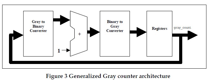
First style gray code counter uses a single set of flip-flops as the Gray code register with accompanying Gray-tobinary conversion, binary increment, and binary-to-Gray conversion.
 module gray_counter(
2
input iclk,3
input irst_n,4
input ivalid,5
output reg [3:0] gray);6
7
wire [3:0] bin_counter;8
wire [3:0] gray_counter;9
10
reg [3:0] G2B_counter;11
12
// convert gray to bin;13
always@(ocounter)14
begin15
G2B_counter[3] = gray[3];16
G2B_counter[2] = gray[2] ^ G2B_counter[3];17
G2B_counter[1] = gray[1] ^ G2B_counter[2];18
G2B_counter[0] = gray[0] ^ G2B_counter[1];19
end20
21
//binary counter increased by one22
assign bin_counter = bin_counter +ivalid;23
24
//convert bin to gray 25
assign gray_counter = (bin_counter >>1) ^ bin_counter;26
27
always@(posedge iclk or negedge irst_n)28
begin29
if(!irst_n)30
begin31
gray <= 4'b0;32
end33
else34
begin35
gray <= gray_counter;36
end37
end38
39
endmodule40
Style #2
A second Gray code counter style, the one described below, uses two sets of registers, one a binary counter and a second to capture a binary-to-Gray converted value. The intent of this Gray code counter style #2 is to utilize the binary carry structure, simplify the Gray-to-binary conversion; reduce combinational logic, and increase the upper frequency limit of the Gray code counter.

module graycounter(2
input iclk,3
input irst_n,4
input ivalid,5
output [ADDSIZE-1 : 0] bin,6
output reg [ADDSIZE : 0] gray);7
8
parameter ADDSIZE = 4;9
10
wire[ADDSIZE : 0] binnext;11
wire[ADDSIZE : 0] graynext;12
reg[ADDSIZE : 0] bin_o;13
14
assign binnext = bin_o + ivalid;15
16
assign graynext = (binnext >>1) ^ binnext;17
18
assign bin = bin_o[ADDSIZE-1 : 0];19
20
always@(posedge iclk or negedge irst_n )21
if(!irst_n)22
 {bin_o, gray} <= 0;

23
else24
{bin_o, gray} <= {binnext, graynext};25
26
27
endmodule28
29
30
31
Reference:
1.Vijay A. Nebhrajani," Asynchronous FIFO Architectures" part2
2. Clifford E. Cummings, Sunburst Design, Inc " Simulation and Synthesis Techniques for Asynchronous
FIFO Design"
posted on 2009-11-03 11:01 Homography Matrix 阅读(6923) 评论(1) 编辑 收藏 举报