

基于MPU6050三轴陀螺仪和三轴加速度传感器姿态识别实验
虽然这里已经提供了获取陀螺仪与加速度相关数据的Arduino示例代码 ,但怎么用这些数据来展现当前的姿态却也还是个问题;后来看到关于ITG3205与ADXL345的姿态识别帖子,然后抄过来一试,效果还真的出来了。
Arduino代码:
    #include "Wire.h"
    #include "I2Cdev.h"
    #include "MPU6050.h"

    MPU6050 accelgyro;

    int16_t ax, ay, az;
    int16_t gx, gy, gz;

    char str[512];

    void setup() {
        Wire.begin();
        Serial.begin(9600);
        accelgyro.initialize();
    }

    void loop() {
        accelgyro.getMotion6(&ax, &ay, &az, &gx, &gy, &gz);
        sprintf(str, "%d,%d,%d,%d,%d,%d,%d", ax, ay, az, gx, gy, gz);
        Serial.print(str);
        Serial.write(byte(10));
        delay(20);
    }
Processing代码:
import processing.serial.*;
Serial myPort; // 创建串口对象myPort
boolean firstSample = true;
float [] RwAcc = new float[3]; // 通过加速度传感器把重力加速度投影在x/y/z三轴上
float [] Gyro = new float[3]; // 陀螺仪读取
float [] RwGyro = new float[3]; // 重新读取陀螺仪
float [] Awz = new float[2]; // XZ/ YZ平面和Z轴(度)R的投影之间的角度
float [] RwEst = new float[3];
int lastTime = 0;
int interval = 0;
float wGyro = 10.0;
int lf = 10; // 10在ASCII表中表示'\n'
byte[] inBuffer = new byte[100];
PFont font;
final int VIEW_SIZE_X = 600, VIEW_SIZE_Y = 600;
void setup()
{
size(VIEW_SIZE_X, VIEW_SIZE_Y, P3D);
//myPort = new Serial(this, Serial.list()[2], 9600); // 设置电脑第三个COM口为连接端口,这个要根据你电脑情况进行设置。
myPort = new Serial(this, "/dev/ttyUSB0", 9600);
// 加载字体,字体必须在代码文件同目录下的data文件夹中
font = loadFont("/home/zwang/processing/processing-1.5.1/modes/android/examples/Basics/Typography/Letters/data/CourierNew36.vlw");
}
void readSensors() {
if (myPort.available() > 0) {
if (myPort.readBytesUntil(lf, inBuffer) > 0) {
String inputString = new String(inBuffer);
String [] inputStringArr = split(inputString, ',');
// 把原始数据转换为G
RwAcc[0] = float(inputStringArr[0]) / 16384.0;
RwAcc[1] = float(inputStringArr[1])/ 16384.0;
RwAcc[2] = float(inputStringArr[2])/ 16384.0;
// 把原始数据转换为"度/秒"
Gyro[0] = float(inputStringArr[3]) / 131.0;
Gyro[1] = float(inputStringArr[4]) / 131.0;
Gyro[2] = float(inputStringArr[5]) / 131.0;
}
}
}
void normalize3DVec(float [] vector) {
float R;
R = sqrt(vector[0]*vector[0] + vector[1]*vector[1] + vector[2]*vector[2]);
vector[0] /= R;
vector[1] /= R;
vector[2] /= R;
}
float squared(float x) {
return x*x;
}
void buildBoxShape() {
//box(60, 10, 40);
noStroke();
beginShape(QUADS);
//Z+ (绘图区域)
fill(#00ff00);
vertex(-30, -5, 20);
vertex(30, -5, 20);
vertex(30, 5, 20);
vertex(-30, 5, 20);
//Z-
fill(#0000ff);
vertex(-30, -5, -20);
vertex(30, -5, -20);
vertex(30, 5, -20);
vertex(-30, 5, -20);
//X-
fill(#ff0000);
vertex(-30, -5, -20);
vertex(-30, -5, 20);
vertex(-30, 5, 20);
vertex(-30, 5, -20);
//X+
fill(#ffff00);
vertex(30, -5, -20);
vertex(30, -5, 20);
vertex(30, 5, 20);
vertex(30, 5, -20);
//Y-
fill(#ff00ff);
vertex(-30, -5, -20);
vertex(30, -5, -20);
vertex(30, -5, 20);
vertex(-30, -5, 20);
//Y+
fill(#00ffff);
vertex(-30, 5, -20);
vertex(30, 5, -20);
vertex(30, 5, 20);
vertex(-30, 5, 20);
endShape();
}
void drawCube() {
pushMatrix();
translate(300, 450, 0);
scale(4, 4, 4);
rotateX(HALF_PI * -RwEst[0]);
rotateZ(HALF_PI * RwEst[1]);
buildBoxShape();
popMatrix();
}
void getInclination() {
int w = 0;
float tmpf = 0.0;
int currentTime, signRzGyro;
readSensors();
normalize3DVec(RwAcc);
currentTime = millis();
interval = currentTime - lastTime;
lastTime = currentTime;
if (firstSample || Float.isNaN(RwEst[0])) { // NaN用来等待检查从arduino过来的数据
for (w=0;w<=2;w++) {
RwEst[w] = RwAcc[w]; // 初始化加速度传感器读数
}
}
else {
// 对RwGyro进行评估
if (abs(RwEst[2]) < 0.1) {
// Rz值非常的小,它的作用是作为Axz与Ayz的计算参照值,防止放大的波动产生错误的结果。
// 这种情况下就跳过当前的陀螺仪数据,使用以前的。
for (w=0;w<=2;w++) {
RwGyro[w] = RwEst[w];
}
}
else {
// ZX/ZY平面和Z轴R的投影之间的角度,基于最近一次的RwEst值
for (w=0;w<=1;w++) {
tmpf = Gyro[w]; // 获取当前陀螺仪的deg/s
tmpf *= interval / 1000.0f; // 得到角度变化值
Awz[w] = atan2(RwEst[w], RwEst[2]) * 180 / PI; // 得到角度并转换为度
Awz[w] += tmpf; // 根据陀螺仪的运动得到更新后的角度
}
// 判断RzGyro是多少,主要看Axz的弧度是多少
// 当Axz在-90 ..90 => cos(Awz) >= 0这个范围内的时候RzGyro是准确的
signRzGyro = ( cos(Awz[0] * PI / 180) >=0 ) ? 1 : -1;
// 从Awz的角度值反向计算RwGyro的公式请查看网页 [url]http://starlino.com/imu_guide.html[/url]
for (w=0;w<=1;w++) {
RwGyro[0] = sin(Awz[0] * PI / 180);
RwGyro[0] /= sqrt( 1 + squared(cos(Awz[0] * PI / 180)) * squared(tan(Awz[1] * PI / 180)) );
RwGyro[1] = sin(Awz[1] * PI / 180);
RwGyro[1] /= sqrt( 1 + squared(cos(Awz[1] * PI / 180)) * squared(tan(Awz[0] * PI / 180)) );
}
RwGyro[2] = signRzGyro * sqrt(1 - squared(RwGyro[0]) - squared(RwGyro[1]));
}
// 把陀螺仪与加速度传感器的值进行结合
for (w=0;w<=2;w++) RwEst[w] = (RwAcc[w] + wGyro * RwGyro[w]) / (1 + wGyro);
normalize3DVec(RwEst);
}
firstSample = false;
}
void draw() {
getInclination();
background(#000000);
fill(#ffffff);
textFont(font, 20);
//float temp_decoded = 35.0 + ((float) (temp + 13200)) / 280;
//text("temp:\n" + temp_decoded + " C", 350, 250);
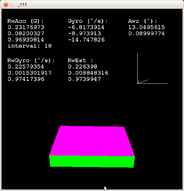
text("RwAcc (G):\n" + RwAcc[0] + "\n" + RwAcc[1] + "\n" + RwAcc[2] + "\ninterval: " + interval, 20, 50);
text("Gyro (°/s):\n" + Gyro[0] + "\n" + Gyro[1] + "\n" + Gyro[2], 220, 50);
text("Awz (°):\n" + Awz[0] + "\n" + Awz[1], 420, 50);
text("RwGyro (°/s):\n" + RwGyro[0] + "\n" + RwGyro[1] + "\n" + RwGyro[2], 20, 180);
text("RwEst :\n" + RwEst[0] + "\n" + RwEst[1] + "\n" + RwEst[2], 220, 180);
// display axes显示轴
pushMatrix();
translate(450, 250, 0);
stroke(#ffffff);
scale(100, 100, 100);
line(0, 0, 0, 1, 0, 0);
line(0, 0, 0, 0, -1, 0);
line(0, 0, 0, 0, 0, 1);
line(0, 0, 0, -RwEst[0], RwEst[1], RwEst[2]);
popMatrix();
drawCube();
}
注意:需要更改上面的 myPort 和 font 的定义。
然后运行Processing就可以看到效果了。
Links:
[1] http://www.geek-workshop.com/thread-1935-1-1.html
[2] http://www.geek-workshop.com/thread-1017-1-1.html
[3] http://www.geek-workshop.com/thread-236-1-1.html
[4] http://blog.sina.com.cn/s/blog_8a49cc8f010167n2.html