Sallen-Key Active Butterworth Low Pass Filter Calculator
RC 2nd Order Passive Low Pass Filter

The cut-off frequency of second order low pass filter is given as

Second order low pass filter -3dB frequency is given as

where ƒc is the calculated cut-off frequency, n is the filter order
and ƒ-3dB is the new -3dB pass band frequency as a result in the increase of the filters order.

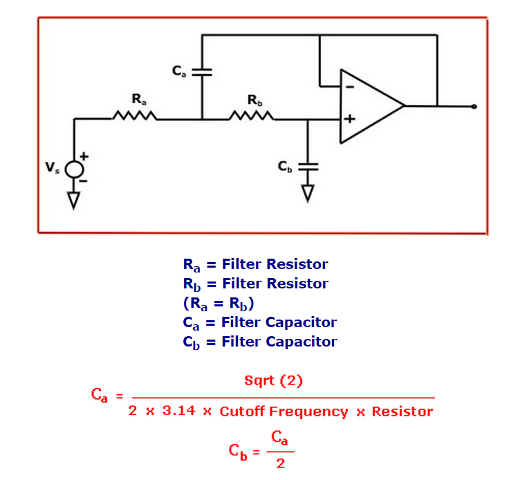
Cutoff Frequency : 50 KHz
Ra : 225 ohm
Rb : 225 ohm
Ca : 20 nF
Cb : 10 nF

Suppose you had a large interfering signal you needed to get rid of.
To get lots of attenuation, you could cascade several RC filters.
Unfortunately, the impedance of one RC section affects the next.
This means that the “knee” or transition between the pass and stop bands won’t be very sharp.
A sharp knee helps you reduce the interfering signal without degrading your desired signals.
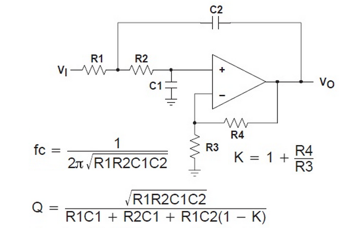
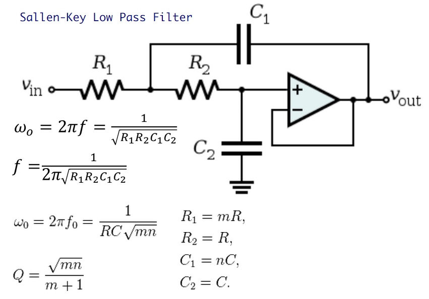
In this situation, the Sallen-Key active filter can save the day.
This circuit implements a 2-pole filter.
Cascading several stages can give you a steep attenuation curve with a very sharp knee.
LOW-PASS FILTER DESIGN
Although there are many filter types and ways to implement them, here’s an active low-pass filter
that’s greatly simplified if R1=R2 and the op amp stage is a unity gain follower (RB=short and RA=open).
Designing a 2-pole Butterworth filter requires just a few steps.
1. Choose a cutoff frequency fo (Hz).
As an example, select fo=10 kHz to reduce a noise signal at 50 kHz and pass your desired signals below 5 kHz.
2. Pick a convenient cap value C2 between 100pF and 0.1 uF.
Suppose you’ve got plenty of 1000pF caps in stock, select this value for C2.
3. Make C1 = 2 x C2
C1 = 2 · C2 = 2000pF
4. Calculate R1 = R2 = 0.707 / (2 · π · fo · C2)
R1 = R2 = 0.707 / (2 · π · 10kHz · 1000pF) = 11.2 K ohms
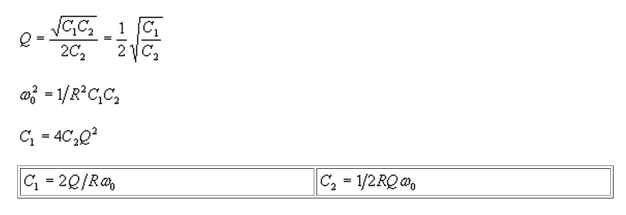
Sallen-Key Low Pass Filter Design Equations
We've created a low pass Butterworth Sallen-Key filter calculator,
which automatically computes the resistor and capacitor values for a filter with a given number of poles.
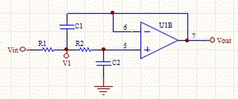
We want to derive a transfer function for the Sallen-Key op-amp circuit in the following form:
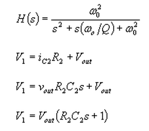
The sum of the currents at node V1.

Substituting for V1
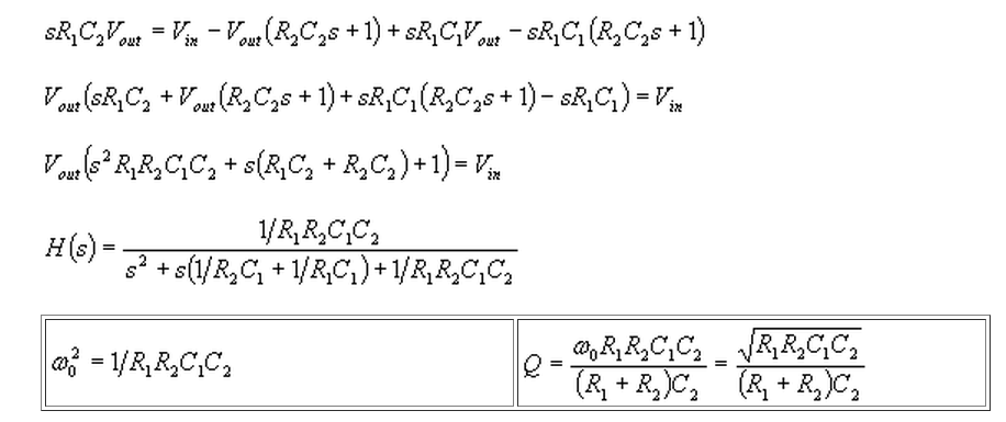
We have more free parameters than we really need so we can set R1=R2=R.
