STM32学习笔记2:起手式
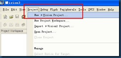
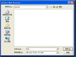
1)打开KEIL3新建工程
工程目录我选择为\C\lab
选择芯片
选择NO
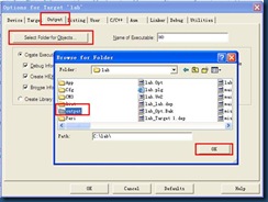
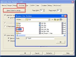
修改工程属性,安放输出文件及LIST文件
安放输出文件
安放LIST文件
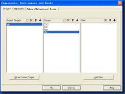
单击工具条下的该按钮,设置工程目录
建立如下目录,同时在工程文件夹下建立同样名字的文件夹
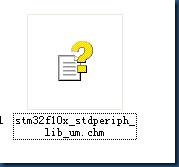
固件库内改说明文档详细说明了改固件库内的内容
\CM3 文件夹存储启动代码,硬核寄存器位置代码
\Peri 文件夹存储外设代码
\Cfg 文件夹存储与软体配置有关的文件
\App 文件夹存储用户自己写的应用程序
(1)\CM3 内代码
根据帮助手册说明
从固件库\Libraries\CMSIS\CM3\DeviceSupport\ST\STM32F10x
获得如下两个文件,这两个是与硬件寄存器有关的
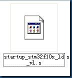
再加入启动代码
从固件库\Libraries\CMSIS\CM3\DeviceSupport\ST\STM32F10x\startup\arm
随便选择一个启动代码,这里选择这个文件:
\Project\STM32F10x_StdPeriph_Template
三个文件全部放入CM3文件夹中,不要忘了在KEIL中添加文件。
(2)\Peri 内代码
将固件库\Libraries\STM32F10x_StdPeriph_Driver内的INC及SRC文件夹内的代码全部拷贝到工程文件夹该目录下,然后添加入KEIL中
(3)\Cfg 内代码
Config文件从给的例程里面选取,到目录\Project\STM32F10x_StdPeriph_Template里面选取文件:
添加完后
(4)\App 内代码
到目录\Project\STM32F10x_StdPeriph_Template里面选取文件:
APP文件夹下的其他的文件就是自己编写的文件了。
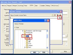
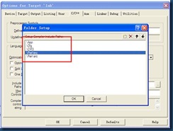
在第一次编译前我们还需要将以上的目录全部添加进入编译器中。
全编译一遍会出现错误
error1:
CM3\stm32f10x.h(80): error: #35: #error directive: "Please select first the target STM32F10x device used in your application (in stm32f10x.h file)"
错误显示位置为:
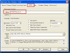
由于我选择的启动代码文件为:startup_stm32f10x_ld_vl.s
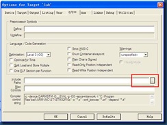
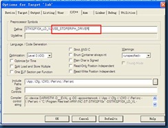
所以我需要添加预先定义符号:
添加完后再编译,该错误消失
error2:
Peri\src\misc.c(98): warning: #223-D: function "assert_param" declared implicitly
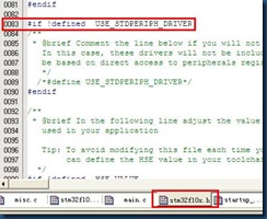
错误位置,如下所示
在同样的位置去定义如下
注意与前面的定义应该有一个空格
再编译除了main.c之外就没有错误了。
2)开始编写main.c
/**
******************************************************************************
* @file GPIO/IOToggle/main.c
* @author MCD Application Team
* @version V3.4.0
* @date 10/15/2010
* @brief Main program body.
******************************************************************************
* @copy
*
* THE PRESENT FIRMWARE WHICH IS FOR GUIDANCE ONLY AIMS AT PROVIDING CUSTOMERS
* WITH CODING INFORMATION REGARDING THEIR PRODUCTS IN ORDER FOR THEM TO SAVE
* TIME. AS A RESULT, STMICROELECTRONICS SHALL NOT BE HELD LIABLE FOR ANY
* DIRECT, INDIRECT OR CONSEQUENTIAL DAMAGES WITH RESPECT TO ANY CLAIMS ARISING
* FROM THE CONTENT OF SUCH FIRMWARE AND/OR THE USE MADE BY CUSTOMERS OF THE
* CODING INFORMATION CONTAINED HEREIN IN CONNECTION WITH THEIR PRODUCTS.
*
* <h2><center>© COPYRIGHT 2010 STMicroelectronics</center></h2>
*/
/* Includes ------------------------------------------------------------------*/
#include "stm32f10x.h"
/** @addtogroup STM32F10x_StdPeriph_Examples
* @{
*/
/** @addtogroup GPIO_IOToggle
* @{
*/
/* Private typedef -----------------------------------------------------------*/
/* Private define ------------------------------------------------------------*/
/* Private macro -------------------------------------------------------------*/
/* Private variables ---------------------------------------------------------*/
GPIO_InitTypeDef GPIO_InitStructure;
/* Private function prototypes -----------------------------------------------*/
void Delay(__IO uint32_t nCount);
/* Private functions ---------------------------------------------------------*/
/**
* @brief Main program.
* @param None
* @retval None
*/
int main(void)
{
/*!< At this stage the microcontroller clock setting is already configured,
this is done through SystemInit() function which is called from startup
file (startup_stm32f10x_xx.s) before to branch to application main.
To reconfigure the default setting of SystemInit() function, refer to
system_stm32f10x.c file
*/
/* Configure all unused GPIO port pins in Analog Input mode (floating input
trigger OFF), this will reduce the power consumption and increase the device
immunity against EMI/EMC *************************************************/
RCC_APB2PeriphClockCmd(RCC_APB2Periph_GPIOB , ENABLE);
GPIO_InitStructure.GPIO_Pin = GPIO_Pin_All;
GPIO_InitStructure.GPIO_Mode = GPIO_Mode_Out_PP;
GPIO_InitStructure.GPIO_Speed=GPIO_Speed_50MHz ;
GPIO_Init(GPIOB, &GPIO_InitStructure);
//RCC_APB2PeriphClockCmd(RCC_APB2Periph_GPIOB , DISABLE);
/* Initialize Leds mounted on STM3210X-EVAL board */
while (1)
{
/* Turn on LD1 */
GPIO_SetBits(GPIOB, GPIO_Pin_8);
/* Insert delay */
Delay(0xAFFFF);
/* Turn off LD1 */
GPIO_ResetBits(GPIOB, GPIO_Pin_8);
/* Insert delay */
Delay(0xAFFFF);
}
}
/**
* @brief Inserts a delay time.
* @param nCount: specifies the delay time length.
* @retval None
*/
void Delay(__IO uint32_t nCount)
{
for(; nCount != 0; nCount--);
}
#ifdef USE_FULL_ASSERT
/**
* @brief Reports the name of the source file and the source line number
* where the assert_param error has occurred.
* @param file: pointer to the source file name
* @param line: assert_param error line source number
* @retval None
*/
void assert_failed(uint8_t* file, uint32_t line)
{
/* User can add his own implementation to report the file name and line number,
ex: printf("Wrong parameters value: file %s on line %d\r\n", file, line) */
/* Infinite loop */
while (1)
{
}
}
#endif
/**
* @}
*/
/**
* @}
*/
/******************* (C) COPYRIGHT 2010 STMicroelectronics *****END OF FILE****/
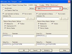
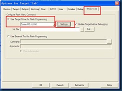
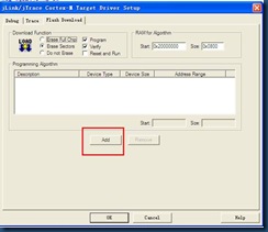
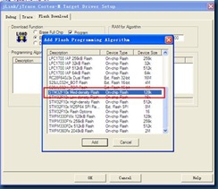
3)设置J-LINK并下载
设置完后就可以下载了,bebug全速运行就可以发现PB8输出的灯在亮。
实验总结
(1)关于GPIOMode结构体的解释:
typedef enum
{ GPIO_Mode_AIN = 0x0,
GPIO_Mode_IN_FLOATING = 0x04,
GPIO_Mode_IPD = 0x28,
GPIO_Mode_IPU = 0x48,
GPIO_Mode_Out_OD = 0x14,
GPIO_Mode_Out_PP = 0x10,
GPIO_Mode_AF_OD = 0x1C,
GPIO_Mode_AF_PP = 0x18
}GPIOMode_TypeDef;
① 浮空输入_IN_FLOATING
② 带上拉输入_IPU
③ 带下拉输入_IPD
④ 模拟输入_AIN
⑤ 开漏输出_OUT_OD
⑥ 推挽输出_OUT_PP
⑦ 复用功能的推挽输出_AF_PP
⑧ 复用功能的开漏输出_AF_OD
(2)在KEIL中的快捷操作
F12 跟进
Ctrl + Tab 返回
Ctrl + F5 DEBUG
F5 全速
F11 单步进函数
F10 单步出函数









【推荐】国内首个AI IDE,深度理解中文开发场景,立即下载体验Trae
【推荐】编程新体验,更懂你的AI,立即体验豆包MarsCode编程助手
【推荐】抖音旗下AI助手豆包,你的智能百科全书,全免费不限次数
【推荐】轻量又高性能的 SSH 工具 IShell:AI 加持,快人一步