(原創) 多工器MUX coding style整理 (SOC) (Verilog) (Quartus II)
Abstract
本文整理出幾種常見的多工器mux可合成的coding style,並深入探討其合成的結果。
Introduction
使用環境:NC-Verilog 5.4 + Debussy 5.4 v9 + Quartus II 8.1
(同一種coding style在不同synthesizer下會有不同的認知,甚至相同synthesizer不同版本也會不同,本文僅討論Quartus II 8.1下的實驗結果)。
各種coding style的RTL Viewer比較
1.使用case
mux_case.v / Verilog
 1 /*
 2 (C) OOMusou 2010 http://oomusou.cnblogs.com
 3
 4 Filename    : mux_case.v
 5 Simulator   : NC-Verilog 5.4 + Debussy 5.4 v9 + Quartus II 8.1
 6 Description : mux by case
 7 Release     : Aug.30,2010 1.0
 8  */
 9
10  module mux_case (
11   a_i,
12   b_i,
13   c_i,
14   d_i,
15   sel_i,
16   q_o
17 );
18
19  input a_i;
20  input b_i;
21  input c_i;
22  input d_i;
23  input [1:0] sel_i;
24  output q_o;
25
26  reg q_o;
27
28  always@(a_i or b_i or c_i or d_i or sel_i) begin
29   case (sel_i)
30     2'b00   : q_o = a_i;
31      2'b01   : q_o = b_i;
32      2'b10   : q_o = c_i;
33      default : q_o = d_i;
34   endcase
35  end
36
37  endmodule
30行
case (sel_i)
  2'b00   : q_o = a_i;
  2'b01   : q_o = b_i;
  2'b10   : q_o = c_i;
  default : q_o = d_i;
endcase
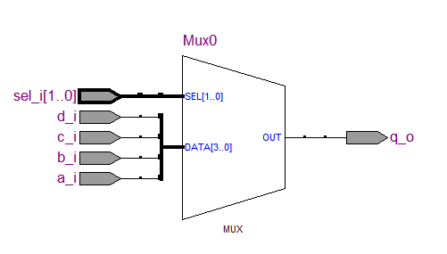
既然心理想的是mux,用case來窮舉自然最一目暸然, 根據[3]Altera所推薦coding style,當使用case時,Quartus II會使用parallel mux來實現。
Testbench
mux_case_tb.v / Verilog
 1 /*
 2 (C) OOMusou 2010 http://oomusou.cnblogs.com
 3
 4 Filename    : mux_case_tb.v
 5 Simulator   : NC-Verilog 5.4 & Debussy 5.4 v9 + Quartus II 8.1
 6 Description : mux by case testbench
 7 Release     : Aug.30,2010 1.0
 8  */
 9
10 `timescale 1 ns/1 ns
11 `include "mux_case.v"
12
13  module mux_case_tb;
14
15  reg a_i, b_i, c_i, d_i;
16  reg [1:0] sel_i;
17  wire q_o;
18
19  initial begin
20   fork
21     #0  a_i   = 1'b0;
22          b_i   = 1'b1;
23          c_i   = 1'b0;
24          d_i   = 1'b1;
25          sel_i = 2'b00;
26
27     #10 sel_i = 2'b01;
28      #20 sel_i = 2'b10;
29      #30 sel_i = 2'b11;
30      #40 sel_i = 2'b00;
31      #50 $finish;
32   join
33  end
34
35  initial begin
36   $fsdbDumpfile("mux_case.fsdb");
37   $fsdbDumpvars(0, mux_case_tb);
38  end
39
40 mux_case u_mux_case (
41   .a_i  (a_i),
42   .b_i  (b_i),
43   .c_i  (c_i),
44   .d_i  (d_i),
45   .sel_i(sel_i),
46   .q_o  (q_o)
47 );
48
49  endmodule
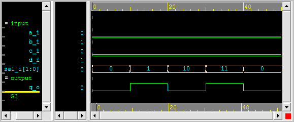
Simulation結果
2.使用if else if
mux_if_else_if.v / Verilog
 1 /*
 2 (C) OOMusou 2010 http://oomusou.cnblogs.com
 3
 4 Filename    : mux_if_else_if.v
 5 Simulator   : NC-Verilog 5.4 + Debussy 5.4 v9 + Quartus II 8.1
 6 Description : mux by if else if
 7 Release     : Aug.30,2010 1.0
 8  */
 9
10  module mux_if_else_if (
11   a_i,
12   b_i,
13   c_i,
14   d_i,
15   sel_i,
16   q_o
17 );
18
19  input a_i, b_i, c_i, d_i;
20  input [1:0] sel_i;
21  output q_o;
22
23  reg q_o;
24
25  always@(sel_i or a_i or b_i or c_i or d_i) begin
26   if (sel_i == 2'b00)
27      q_o = a_i;
28   else if (sel_i == 2'b01)
29      q_o = b_i;
30   else if (sel_i == 2'b10)
31      q_o = c_i;
32   else
33     q_o = d_i;
34  end
35
36  endmodule
26行
if (sel_i == 2'b00)
  q_o = a_i;
else if (sel_i == 2'b01)
  q_o = b_i;
else if (sel_i == 2'b10)
  q_o = c_i;
else
  q_o = d_i;
使用if else if來描述mux也是常見的coding style, 根據[3]Altera所推薦coding style,當使用if else if時,會使用priority mux來實現。
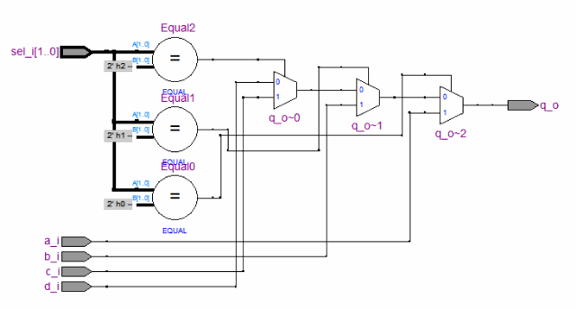
這篇博文會卡這麼久,除了工作了只能用下班時間寫博文以外,對於if else if是否會有priority,我ㄧ直很不確定,因為各種所查到的資料講法都不一樣,在[3] Quartus II 8.1 Handbook Volumn 1, Chapter 1:Recommended HDL Coding Styles與[4] 特權同學的深入淺出玩轉FPGA的p.19中,都認為if else if會有priority,由RTL Viewer看來也是如此, 但在[5] Guide to HDL Coding Style for Synthesis p.1-7與[6] 劉福奇, 劉波 2010, Verilog HDL應用程序設計實例精講, 電子工業出版社的p.217,都認為if else if與case意義相同無priority,所以看起來if else if的認知與synthesizer有強烈的關係,我個人是傾向Altera所建議的coding style:case代表parallel mux,if else if代表priority mux。
testbench與simulation結果與使用case都一樣,所以省略。
3.使用?:
mux_ternary.v / Verilog
 1 /*
 2 (C) OOMusou 2010 http://oomusou.cnblogs.com
 3
 4 Filename    : mux_ternary.v
 5 Simulator   : NC-Verilog 5.4 + Debussy 5.4 v9 + Quartus II 8.1
 6 Description : mux by ?:
 7 Release     : Aug.30,2010 1.0
 8  */
 9
10 `timescale 1 ns/1 ns
11
12  module mux_ternary (
13   a_i,
14   b_i,
15   c_i,
16   d_i,
17   sel_i,
18   q_o
19 );
20
21  input a_i, b_i, c_i, d_i;
22  input [1:0] sel_i;
23  output q_o;
24
25  assign q_o = (sel_i == 2'b00) ? a_i :
26               (sel_i == 2'b01) ? b_i :
27               (sel_i == 2'b10) ? c_i :
28                                  d_i;
29
30  endmodule
25行
assign q_o = (sel_i == 2'b00) ? a_i :
             (sel_i == 2'b01) ? b_i :
             (sel_i == 2'b10) ? c_i :
                                d_i;
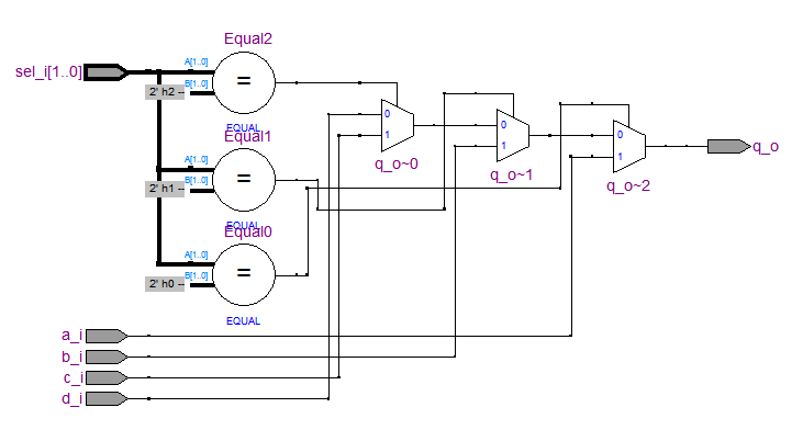
有些人的coding style是always只給sequential logic,若純combinational logic則用?:表示,為了與always做區隔,這種寫法其實跟if else if完全一樣,在Quartus II的RTL Viewer也完全一樣,都是使用priority mux實現。
4:使用步林運算式
mux_assign.v / Verilog
 1 /*
 2 (C) OOMusou 2010 http://oomusou.cnblogs.com
 3
 4 Filename    : mux_assign.v
 5 Simulator   : NC-Verilog 5.4 + Debussy 5.4 v9 + Quartus II 8.1
 6 Description : mux by assign
 7 Release     : Sep.22,2010 1.0
 8  */
 9
10  module mux_assign (
11   a_i,
12   b_i,
13   c_i,
14   d_i,
15   sel_i,
16   q_o
17 );
18
19  input a_i;
20  input b_i;
21 input c_i;
22 input d_i;
23 input [1:0] sel_i;
24 output q_o;
25
26 assign q_o = (~sel_i[1] & ~sel_i[0] & a_i) |
27              (~sel_i[1] &  sel_i[0] & b_i) |
28              ( sel_i[1] & ~sel_i[0] & c_i) |
29              ( sel_i[1] &  sel_i[0] & d_i);
30
31 endmodule
這是最基本的作法,只要剛開始學邏輯設計就會這招,雖然很低階,但很多時候這種方式這種方式卻是最實用的,而且也不花俏,Synthesizer一定看的懂。

前4種都是正統推薦的寫法,後面要講的都是不推薦的寫法,主要是讓我們知道這樣為什麼不好,並不是鼓勵大家這樣寫。
5.使用multiple if
mux_multi_if.v / Verilog
 1 /*
 2 (C) OOMusou 2010 http://oomusou.cnblogs.com
 3
 4 Filename    : mux_mult_if.v
 5 Simulator   : NC-Verilog 5.4 + Debussy 5.4 v9 + Quartus II 8.1
 6 Description : mux by mutiple if
 7 Release     : Sep.1,2010 1.0
 8  */
 9
10 `timescale 1 ns/1 ns
11
12  module mux_multi_if (
13   a_i,
14   b_i,
15   c_i,
16   d_i,
17   sel_i,
18   q_o
19 );
20
21  input a_i, b_i, c_i, d_i;
22  input [1:0] sel_i;
23  output q_o;
24
25  reg q_o;
26
27  always@(sel_i or a_i or b_i or c_i or d_i) begin
28   q_o = 1'bx;
29
30   if (sel_i == 2'b00)
31      q_o = a_i;
32
33   if (sel_i == 2'b01)
34      q_o = b_i;
35
36   if (sel_i == 2'b10)
37      q_o = c_i;
38
39   if (sel_i == 2'b11)
40      q_o = d_i;
41  end
42
43  endmodule
這種寫法比較少見,但偶而還是會看到有人會用multi if來寫,若以C與simulation的角度來看,這種寫法邏輯絕對正確,但若以synthesizer的角度來看,由於每個if都沒有else,在[3] Altera所建議的coding style中,沒有else的就暗示有latch,儘管multi if將所有的條件都列出而不該有latch,但這種寫法會增加synthesizer的判斷難度而造成誤判,所以較不推薦這種寫法。
28行
q_o = 1'bx;
還特別將q_o加一個default值為don't care(unknown對synthesizer為don't care),若不加這個don't care,RTL Viewer會多合出1個latch,稍後會解釋。
30行
if (sel_i == 2'b00)
    q_o = a_i;

if (sel_i == 2'b01)
    q_o = b_i;

if (sel_i == 2'b10)
    q_o = c_i;

if (sel_i == 2'b11)
    q_o = d_i;
使用multi if列出所有條件。
至於這樣代表什麼電路呢?在[3] Altera所建議的coding style並沒有明確的講是什麼電路,在[4] 特權同學的深入淺出玩轉FPGA的p.27,認為multi if跟case一樣,會合成出parallel mux,在其他的書大都認為multi if合成出priority mux,在Quartus II的RTL Viewer看到的也是priority mux。
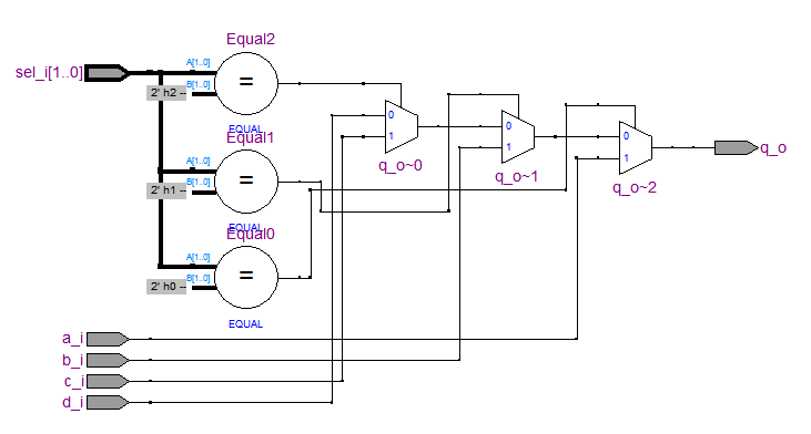
我個人的認知也是頃向priority mux。
回到之前的問題,若沒加上q_o = 1'bx 會如何呢?
reg q_o;

always@(sel_i or a_i or b_i or c_i or d_i) begin
  if (sel_i == 2'b00)
    q_o = a_i;

  if (sel_i == 2'b01)
    q_o = b_i;

  if (sel_i == 2'b10)
    q_o = c_i;

  if (sel_i == 2'b11)
    q_o = d_i;
end
對pre sim來說,這樣也完全正確,但對Quartus II來說,已經提出了warning
Warning (10240): Verilog HDL Always Construct warning at mux_multi_if.v(27): inferring latch(es) for variable "q_o", which holds its previous value in one or more paths through the always construct

Warning: LATCH primitive "q_o$latch" is permanently enabled
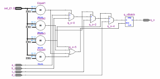
由RTL Viewer觀察,也真的多出了latch,並且從原本3個比較器變成4個comparator,因為你動用了4個if,所以合出4個comparator似乎也是合理。
除此之外,或許你會問:『在RTL用unknown不太好吧,RTL應該只有0或1,unknown會讓synthesizer認為don't care,可能0或1,而造成pre-sim與post-sim結果不一樣。』
在絕大部分狀況下,RTL都不該用unknown,應該給default值0或者1,但這裡比較特別,因為後面的if是full case,也就是列出了所有狀況,會自動蓋掉default的unknown,而unknown只希望告訴synthesizer default就是don't care,要synthesizer不用去合成出latch,而且也因為後面的if是full case,並不會造成pre-sim與post-sim結果不同。
若將default改成0,結果會怎樣呢?
reg q_o;

always@(sel_i or a_i or b_i or c_i or d_i) begin
  q_o = 1'b0;

  if (sel_i == 2'b00)
    q_o = a_i;

  if (sel_i == 2'b01)
    q_o = b_i;

  if (sel_i == 2'b10)
    q_o = c_i;

  if (sel_i == 2'b11)
    q_o = d_i;
end
Quartus II不再會有產生latch的警告,不過RTL Viewer卻不是很理想。
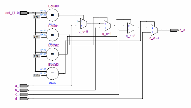
Quartus II使用了4個mux與4個comparator與4個mux,雖然已經沒有latch,但還是沒有使用q_o = 1'bx的結果好。
由此可知,使用multi if的寫法,真的造成synthesizer很大的負擔,在這麼簡單的程式中,就已經搞成這樣,很難想像在真的project中,那種複雜的程式結果會怎樣,所以不建議使用multi if寫法。
6.使用2層nested if
mux_nested_if.v / Verilog
 1 /*
 2 (C) OOMusou 2010 http://oomusou.cnblogs.com
 3
 4 Filename    : mux_nested_if_2.v
 5 Simulator   : NC-Verilog 5.4 + Debussy 5.4 v9 + Quartus II 8.1
 6 Description : mux by 2 nested if
 7 Release     : Aug.30,2010 1.0
 8 */
 9
10 module mux_nested_if_2 (
11   a_i,
12   b_i,
13   c_i,
14   d_i,
15   sel_i,
16   q_o
17 );
18
19 input a_i;
20 input b_i;
21 input c_i;
22 input d_i;
23 input [1:0] sel_i;
24 output q_o;
25
26 reg q_o;
27
28 always@(a_i or b_i or c_i or d_i or sel_i) begin
29   if (~sel_i[1])
30     if (~sel_i[0])
31       q_o = a_i;
32     else
33       q_o = b_i;
34   else
35     if (~sel_i[0])
36       q_o = c_i;
37     else
38       q_o = d_i;
39 end
40
41 endmodule
29行
if (~sel_i[1])
  if (~sel_i[0])
    q_o = a_i;
  else
    q_o = b_i;
else
  if (~sel_i[0])
    q_o = c_i;
  else
    q_o = d_i;
根據每個bit而使用nested if來描述mux,在[1] Douglas J. Smith, HDL Chip Design, A practical guide for designing, synthesizing and simulating ASICs and FPGAs using VHDL or Verilog的p.138出現這種寫法,在實務上,我發現有軟體背景的人寫RTL比較容易出現這種寫法,因為在C中,nested if相當自然,但硬體背景的人不太會寫nested if,因為知道巢狀寫的越深,則電路延遲就越大,因此巢狀延伸的層數不宜太多,以免電路跑不快[2],也就是fmax會較差,因為可能產生critical path。
若依照原本的程式,應該合成出以下的電路。

不過現在synthesizer都很聰明,對於巢狀if通常都會看的懂,自動會用parallel mux去實現。
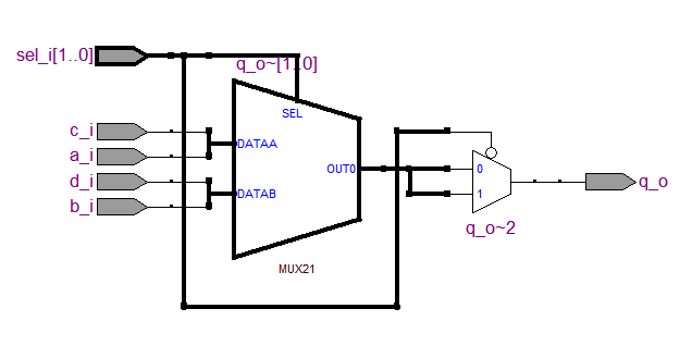
Quartus II在這裡有點搞笑,已經用parallel mux去實現了,但最後又多了一個mux,而且0與1還接同一個out0,擺明了這個mux根本無用,我是不懂為什麼Quartus II會這樣子合成,不知道Quartus II新版本會不會有改進(後來我裝了最新的Quartus II 10.0後,結果還是一樣沒變)。
在此我們看到了nested if雖然也能代表mux,但卻必須強烈依賴synthesizer的合成功力,與其如此,還不如coder自己在code就能掌握要合成什麼電路,所以也不太建議使用巢狀if來寫mux。
7.使用3層nested if
mux_nested_if_3.v / Verilog
 1 /*
 2 (C) OOMusou 2010 http://oomusou.cnblogs.com
 3
 4 Filename    : mux_nested_if_3.v
 5 Simulator   : NC-Verilog 5.4 + Debussy 5.4 v9 + Quartus II 8.1
 6 Description : mux by 3 nested if
 7 Release     : Sep.1,2010 1.0
 8 */
 9
10 module mux_nested_if_3 (
11   a_i,
12   b_i,
13   c_i,
14   d_i,
15   sel_i,
16   q_o
17 );
18
19 input a_i;
20 input b_i;
21 input c_i;
22 input d_i;
23 input [1:0] sel_i;
24 output q_o;
25
26 reg q_o;
27
28 always@(a_i or b_i or c_i or d_i or sel_i) begin
29   if (sel_i == 2'b00)
30       q_o = a_i;
31   else begin
32     if (sel_i == 2'b01)
33       q_o = b_i;
34     else begin
35       if (sel_i == 2'b10)
36         q_o = c_i;
37       else
38         q_o = d_i;
39     end
40   end
41 end
42
43 endmodule
32行
if (sel_i == 2'b00)
  q_o = a_i;
else begin
  if (sel_i == 2'b01)
    q_o = b_i;
  else begin
    if (sel_i == 2'b10)
      q_o = c_i;
    else
      q_o = d_i;
  end
end
使用了3層nested if,初學者很容易寫出這種code,先不討論Verilog,若以C的觀點,表面上雖然是3層if,若仔細的去思考,其實它的意義與使用if else if是相同的。
if (sel_i == 2'b00)
  q_o = a_i;
else if (sel_i == 2'b01)
  q_o = b_i;
else if (sel_i == 2'b10)
  q_o = c_i;
else
  q_o = d_i;
所以這種是假的3層nested if,Quartus II在合成時,與第2種方法:使用if else if的結果完全一樣。
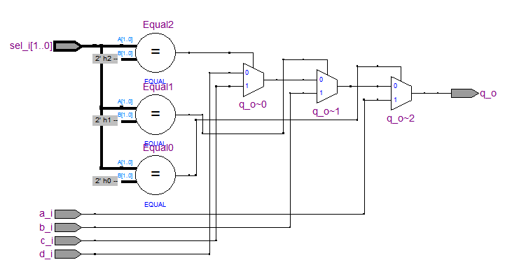
這告訴我們,若寫出3層以上的nested if時,可以冷靜思考真的需要嗎?是不是其實一層的if esle if就可以實現了,雖然可能不會影響最後合成結果,但最少code的可讀性更高。
8.使用case(1)
mux_case_1.v / Verilog
 1 /*
 2 (C) OOMusou 2010 http://oomusou.cnblogs.com
 3
 4 Filename    : mux_case_1.v
 5 Simulator   : NC-Verilog 5.4 + Debussy 5.4 v9 + Quartus II 8.1
 6 Description : mux by case_1
 7 Release     : Sep.1,2010 1.0
 8 */
 9
10 module mux_case_1 (
11   a_i,
12   b_i,
13   c_i,
14   d_i,
15   sel_i,
16   q_o
17 );
18
19 input a_i;
20 input b_i;
21 input c_i;
22 input d_i;
23 input [1:0] sel_i;
24 output q_o;
25
26 reg q_o;
27
28 always@(a_i or b_i or c_i or d_i or sel_i) begin
29   case (1) // synthesis parallel_case full_case
30     (sel_i == 2'b00) : q_o = a_i;
31     (sel_i == 2'b01) : q_o = b_i;
32     (sel_i == 2'b10) : q_o = c_i;
33     (sel_i == 2'b11) : q_o = d_i;
34   endcase
35 end
36
37 endmodule
29行
case (1) // synthesis parallel_case full_case
  (sel_i == 2'b00) : q_o = a_i;
  (sel_i == 2'b01) : q_o = b_i;
  (sel_i == 2'b10) : q_o = c_i;
  (sel_i == 2'b11) : q_o = d_i;
endcase
首先我必須承認這是很變態的寫法,不值得學習, 但當成Verilog語法的學習倒可以,順便知道這樣為什麼不好。
先看合成結果,會使用1個parallel mux與4個comparator,這與預期符合,雖然不像第一種寫法直接用case這麼漂亮,但最少已經用了parallel mux,且沒有priority,而且4個compartor也在預期當中。
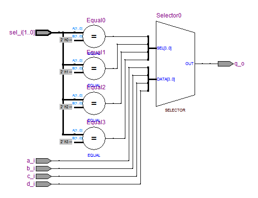
但這是要付出代價的,動用了parallel_case與full_case 2個synthesis directive!!
之所以會這樣寫,主要是因為Verilog提供了一個大部分語言(包括VHDL、C/C++、C#、Java、JavaScript、VB..)所沒有的神奇功能,目前僅在VB.NET看到過有這種寫法,在case item竟然可以擺運算式,若你在C這樣寫,會給你『case expression not constant』的錯誤訊息,VHDL也規定case item必須是常數,這導致Verilog的case可以寫出"case if true"的coding style,也就是在case中寫if else if的感覺。
由於case expression形同虛設,主要都在case item判斷,所以case expression只要給1就行。
但case (1)的問題來了,synthesizer無法藉由case expression與case item來判斷是否為full case,所以當Quartus II遇到你用case (1)寫法時,會出下以下warning。
Warning (10763): Verilog HDL warning at mux_case_1.v(29): case statement has overlapping case item expressions with non-constant or don't care bits - unable to check case statement for completeness
所以這時候就該適時使用 // synthesis full_case 來告訴Quartus II:『我這個case是full的!!』 。一般來說,// synthesis full_case 被誤用都是因為本來不是full case,硬使用 // synthesis full_case 而造成pre-sim與post-sim結果不一樣,我們這個例子因為肯定是full case,所以不會造成pre-sim與post-sim不同。
除此之外,case (1)因為是"case if true",所以synthesizer很容易當成if else if的方式認知,而合成出具有priority的電路,所以case (1)寫法時,通常會搭配 // synthesis parallel_case,這也是為什麼這個例子要同時使用full_case與parallel_case。
若沒加上//synthesis full_case parallel_case會怎樣呢?
case (1)
  (sel_i == 2'b00) : q_o = a_i;
  (sel_i == 2'b01) : q_o = b_i;
  (sel_i == 2'b10) : q_o = c_i;
  (sel_i == 2'b11) : q_o = d_i;
endcase
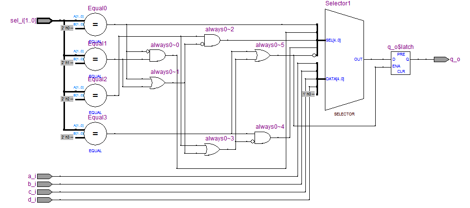
夠慘吧,不知道在合什麼,而且還有latch。
結論還是不贊成這樣寫,通常case (1)都不是好coding style [7],除非用在one-hot encoding時 [7],以後會有專文討論。這裡只是順便用來展示Verilog case (1)這種獨門絕技,並且適時搭配// synthesis full_case 與 // synthesis parallel_case。
以上是我目前所知能合成出mux的8種coding style,若你還知道其他寫法,請告訴我。其中前4種為推荐的寫法,後4種並不推薦。
各種coding style的Technology Map Viewer比較
若去比較以上7種寫法的所佔用資源的狀況,會有驚人的發現,雖然7種寫法的RTL Viewer不一樣,但最後mapping的結果卻完全一樣,僅佔2個LE。
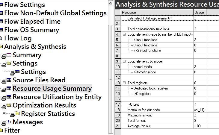
再打開Technology Map Viewer一看,7種寫法也完全一樣,都只佔用了2個LE,而且是完全利用2個LE(這也是為什麼我舉4對1 mux為例的意義,稍後要講的Restructure Multiplexer選項就是利用4對1 mux能完全利用2個LE的優點來減少LE的使用),也就是說,無論你code怎麼寫,最後在FPGA都是一樣的,最後都是用parallel mux實現。

難怪很多人說,RTL Viwer只能參考用,畢竟這只是Quartus II初步對你code認知的結果,要到mapping之後,才能完全確定Quartus II是如何實現,因為Cyclone系列一個LE的LUT是基於4 input,所以一個1個4x1 mux加上sel_i[1:0]一共6個input,就要動用2個LE,若是Stratix系列,一個LE的LUT是基於6 input,就只需1個LE就能搞定。
Quartus II對mux的優化選項
Quartus II另外提供了對mux的優化選項,以Quartus II 8.1來說,在Assignments –> Settings –> Analysis & Synthesis Settings的Restructure Multiplexers。
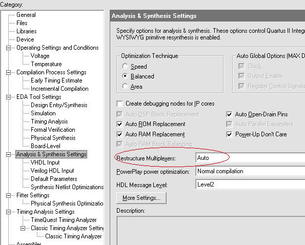
以下是Tcl的方式:(on/off/auto可自己更改)
set_global_assignment -name mux_restructure on
首先簡單的談這個選項的意義,因為FPGA是基於4 input LUT(以Cyclone為例), 若你寫了很多的if,基本上每個if都會是一個2對1的mux,對1個LE來說,只用了3個input,另外1個input就空著沒用,等下一個2對1的mux需要時,又是另外開一個LE,這樣就造成了LE的浪費,若使用了Restruecture Multiplexer後,Quartus II會在truth table結果不變的前提下,重新將2對1的mux組合成4對1的mux,由上面的例子可知,4對1的mux剛好2個LE用滿,沒有浪費,這樣LE的利用率就越高,就可越節省LE的使用,當然代價就是需要另外用control logic去做轉換,combinational logic gate delay會較大,Fmax會較差。在[7] Multiplexer Restructuring for FPGA Implementation Cost Reduction中,有對Restruecture Multiplexer演算法詳細的描述,以下引兩張該paper的圖解釋。
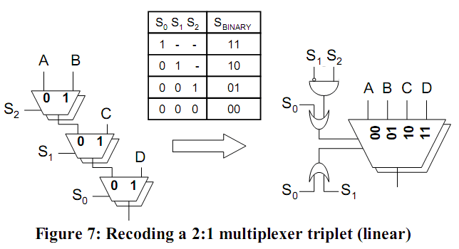
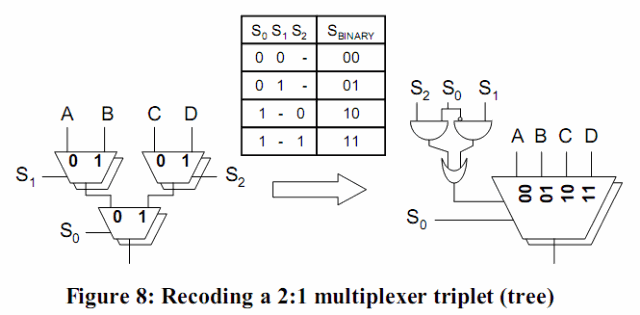
原來2對1 mux tree被restructure成4對1 mux並帶一些control logic,因為4對1 max可以完全利用2個4 input LUT的LE,如此可大大增加LE的使用率,而節省LE的使用。當然這只是最初步的解釋,詳細還是請參考[7] Multiplexer Restructuring for FPGA Implementation Cost Reduction,這是Altera原廠的paper。
根據[3] Quartus II 8.1 Handbook Volume 1, Section III Synthesis, Chapter 8, Quartus II Synthesis Options : Restructure Multiplexers的解釋,這個設定可以有三種選項:
On : 永遠執行mux restructure來減少LE,但有可能使Fmax變差(因為多了control logic後,gate delay較大,所以Fmax會較差)。
Off:永遠不執行mux restructure。
Auto:(default) 當Optimization Technique選Speed、Balance或者Area時,會自動執行mux restructure,尤其當選擇speed時,會選擇性的restructure mux,已達成speed的需求,並且也能減少LE的使用率。
完整程式碼下載
mux_case.7z (使用case)
mux_if_else_if.7z (使用if else if)
mux_ternary.7z (使用?:)
mux_assign.7z (使用步林運算式)
mux_multi_if.7z (使用multi if)
mux_nested_if_2.7z (使用2層nested if)
mux_nested_if_3.7z (使用3層nested if)
mux_case_1.7z (使用 case (1))
Conclusion
1.Verilog是HDL,寫法要保守
之前的博文我就已經多次強調過,Verilog是HDL,是硬體描述語言,而不是硬體程式語言,所以絕對不能像寫C一樣,寫C只要語法對,邏輯對,C compiler就看的懂,你也不用去考慮C compiler會編譯成什麼組合語言,更不能像C++一樣,一味的追求語法華麗,而產生出像template或STL, boost那種看起來很爽的寫法,寫Verilog時,自己一定要能清楚掌握你想要合成出什麼樣的硬體,然後用synthesizer能看的懂得寫法去寫,而不是只求Verilog語法邏輯正確,或者語法簡潔華麗,卻不知道synthesizer最後會合成出什麼硬體。其實好的RTL都很樸實,就是always block,if else if描述條件,case描述FSM,偶爾搭配?:,大概就這4種寫法就打死一切了,並沒有用什麼高級的寫法。樸實的寫法除了讓synthesizer看的懂外,在ASIC開發時,最後總逃不過ECO,若連你自己都不知道code會合成出什麼硬體,要怎麼去做ECO呢?
2.多層if時,考慮重新思考
初學者由於受C語言影響,很容易寫出多層nested if的程式,由以上的經驗可發現,2層與3層的if都可以化簡成if else if或者case,所以真的寫出多層if時,可以重新考慮是否有化簡的可能,畢竟恐龍級的nested if並不好閱讀。
3.在FPGA,RTL Viewer並不是最後的結果,Technology Map Viewer才是最後結果
由於FPGA的工藝是採用4 input LUT的LE,與ASIC不一樣,所以不能光看RTL Viewer就斷定合成的結果,而必須看過經過mapping後的Technology Map Viewer才能真正確定是如何在FPGA實現。雖然以上7個coding style在Altera FPGA結果都一樣,但也不代表RTL我們可以亂寫,雖然synthesizer的優化演算法一直在進步,但身為coder卻不能完全去依賴synthesizer的優化能力,而是應該培養好的coding style習慣,而不是在測試synthesizer的極限。基本上mux所建議的coding style就是case、if else if與?:,其他寫法都不建議。好的coding style除了有助於synthesizer合成外,對日後維護也是很有幫助。
Reference
[1] Douglas J. Smith, HDL Chip Design, A practical guide for designing, synthesizing and simulating ASICs and FPGAs using VHDL or Verilog
[2] 鄭羽伸 2006, Verilog數位電路設計範例寶典基礎篇, 儒林圖書出版社
[3] Quartus II 8.1 Handbook Volume 1, Chapter 6:Recommended HDL Coding Styles
[4] 特權同學 2010, 深入淺出玩轉FPGA, 北京航空航天大學出版社
[5] 1999, Guide to HDL Conding Style for Synthesis
[6] 劉福奇, 劉波 2010, Verilog HDL應用程序設計實例精講, 電子工業出版社
[7] Cliff Cummings 1999, "full_case parallel_case", the Evil Twins of Verilog Synthesis, Sunburst Design
[8] Paul Metzgen, Dominic Nancekievill 2005, Multiplexer Restructuring for FPGA Implementation Cost Reduction, Altera European Technology Center
[9] 廖裕評, 陸瑞強 2006, 系統晶片設計 使用Quartus II, 全華科技圖書股份有限公司
全文完。


 浙公网安备 33010602011771号