好了现在来step by step来生成SPI的查询工程


设置时钟源为外部晶振

开启调试接口(SWD)

设置使用SPI1
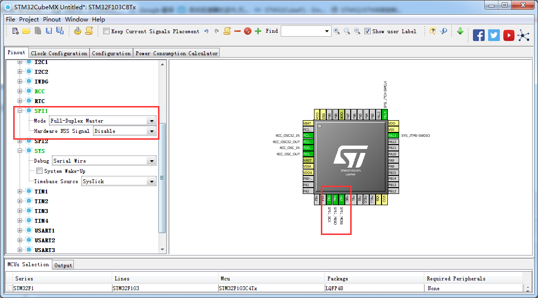
设置SPI的cs管脚

设置时钟树

对SPI的配置进行配置(如果对SPI一些配置不理解的话可以参考 SPI线协议详解 )

修改PA4在初始化的输出电平为高电平

对管脚的重新命名(备注可以根据自己的命名生成相应的宏定义)


我们检查重新命名后管脚

设置工程文件路径等

生成工程


我们在main中新增代码后如下:【下面的代码主要进行HAL_SPI_Transmit的测试】【测试未接spi设备】


/**
  ******************************************************************************
  * File Name          : main.c
  * Description        : Main program body
  ******************************************************************************
  ** This notice applies to any and all portions of this file
  * that are not between comment pairs USER CODE BEGIN and
  * USER CODE END. Other portions of this file, whether
  * inserted by the user or by software development tools
  * are owned by their respective copyright owners.
  *
  * COPYRIGHT(c) 2017 STMicroelectronics
  *
  * Redistribution and use in source and binary forms, with or without modification,
  * are permitted provided that the following conditions are met:
  *   1. Redistributions of source code must retain the above copyright notice,
  *      this list of conditions and the following disclaimer.
  *   2. Redistributions in binary form must reproduce the above copyright notice,
  *      this list of conditions and the following disclaimer in the documentation
  *      and/or other materials provided with the distribution.
  *   3. Neither the name of STMicroelectronics nor the names of its contributors
  *      may be used to endorse or promote products derived from this software
  *      without specific prior written permission.
  *
  * THIS SOFTWARE IS PROVIDED BY THE COPYRIGHT HOLDERS AND CONTRIBUTORS "AS IS"
  * AND ANY EXPRESS OR IMPLIED WARRANTIES, INCLUDING, BUT NOT LIMITED TO, THE
  * IMPLIED WARRANTIES OF MERCHANTABILITY AND FITNESS FOR A PARTICULAR PURPOSE ARE
  * DISCLAIMED. IN NO EVENT SHALL THE COPYRIGHT HOLDER OR CONTRIBUTORS BE LIABLE
  * FOR ANY DIRECT, INDIRECT, INCIDENTAL, SPECIAL, EXEMPLARY, OR CONSEQUENTIAL
  * DAMAGES (INCLUDING, BUT NOT LIMITED TO, PROCUREMENT OF SUBSTITUTE GOODS OR
  * SERVICES; LOSS OF USE, DATA, OR PROFITS; OR BUSINESS INTERRUPTION) HOWEVER
  * CAUSED AND ON ANY THEORY OF LIABILITY, WHETHER IN CONTRACT, STRICT LIABILITY,
  * OR TORT (INCLUDING NEGLIGENCE OR OTHERWISE) ARISING IN ANY WAY OUT OF THE USE
  * OF THIS SOFTWARE, EVEN IF ADVISED OF THE POSSIBILITY OF SUCH DAMAGE.
  *
  ******************************************************************************
  */
/* Includes ------------------------------------------------------------------*/
#include "main.h"
#include "stm32f1xx_hal.h"

/* USER CODE BEGIN Includes */

/* USER CODE END Includes */

/* Private variables ---------------------------------------------------------*/
SPI_HandleTypeDef hspi1;

/* USER CODE BEGIN PV */
/* Private variables ---------------------------------------------------------*/

/* USER CODE END PV */

/* Private function prototypes -----------------------------------------------*/
void SystemClock_Config(void);
static void MX_GPIO_Init(void);
static void MX_SPI1_Init(void);

/* USER CODE BEGIN PFP */
/* Private function prototypes -----------------------------------------------*/

/* USER CODE END PFP */

/* USER CODE BEGIN 0 */

/* USER CODE END 0 */

int main(void)
{

  /* USER CODE BEGIN 1 */
  uint8_t address,data;
  /* USER CODE END 1 */

  /* MCU Configuration----------------------------------------------------------*/

  /* Reset of all peripherals, Initializes the Flash interface and the Systick. */
  HAL_Init();

  /* USER CODE BEGIN Init */

  /* USER CODE END Init */

  /* Configure the system clock */
  SystemClock_Config();

  /* USER CODE BEGIN SysInit */

  /* USER CODE END SysInit */

  /* Initialize all configured peripherals */
  MX_GPIO_Init();
  MX_SPI1_Init();

  /* USER CODE BEGIN 2 */

  /* USER CODE END 2 */

  /* Infinite loop */
  /* USER CODE BEGIN WHILE */
  while (1)
  {
  /* USER CODE END WHILE */

  /* USER CODE BEGIN 3 */
    //Function1: HAL_SPI_Transmit()
    //Function2: HAL_SPI_Receive()

    //(1):SPI Tranamit, write to CNTRL reg1 on address 0x20
    //Step(1):Bring the CS pin low to activate the slave device
    HAL_GPIO_WritePin(GPIOA, GPIO_PIN_4, GPIO_PIN_RESET);
    //Step(2):Transmit address
    address = 0x20;
    HAL_SPI_Transmit(&hspi1,&address,1,50);
    //Step(3):Transmit the date to write to register
    data = 0x67;
    HAL_SPI_Transmit(&hspi1,&data,1,50);
    //Step(4):Bring CS pin High again
    HAL_GPIO_WritePin(GPIOA, GPIO_PIN_4, GPIO_PIN_SET);
  }
  /* USER CODE END 3 */

}

/** System Clock Configuration
*/
void SystemClock_Config(void)
{

  RCC_OscInitTypeDef RCC_OscInitStruct;
  RCC_ClkInitTypeDef RCC_ClkInitStruct;

    /**Initializes the CPU, AHB and APB busses clocks
    */
  RCC_OscInitStruct.OscillatorType = RCC_OSCILLATORTYPE_HSE;
  RCC_OscInitStruct.HSEState = RCC_HSE_ON;
  RCC_OscInitStruct.HSEPredivValue = RCC_HSE_PREDIV_DIV1;
  RCC_OscInitStruct.HSIState = RCC_HSI_ON;
  RCC_OscInitStruct.PLL.PLLState = RCC_PLL_ON;
  RCC_OscInitStruct.PLL.PLLSource = RCC_PLLSOURCE_HSE;
  RCC_OscInitStruct.PLL.PLLMUL = RCC_PLL_MUL9;
  if (HAL_RCC_OscConfig(&RCC_OscInitStruct) != HAL_OK)
  {
    _Error_Handler(__FILE__, __LINE__);
  }

    /**Initializes the CPU, AHB and APB busses clocks
    */
  RCC_ClkInitStruct.ClockType = RCC_CLOCKTYPE_HCLK|RCC_CLOCKTYPE_SYSCLK
                              |RCC_CLOCKTYPE_PCLK1|RCC_CLOCKTYPE_PCLK2;
  RCC_ClkInitStruct.SYSCLKSource = RCC_SYSCLKSOURCE_PLLCLK;
  RCC_ClkInitStruct.AHBCLKDivider = RCC_SYSCLK_DIV1;
  RCC_ClkInitStruct.APB1CLKDivider = RCC_HCLK_DIV2;
  RCC_ClkInitStruct.APB2CLKDivider = RCC_HCLK_DIV1;

  if (HAL_RCC_ClockConfig(&RCC_ClkInitStruct, FLASH_LATENCY_2) != HAL_OK)
  {
    _Error_Handler(__FILE__, __LINE__);
  }

    /**Configure the Systick interrupt time
    */
  HAL_SYSTICK_Config(HAL_RCC_GetHCLKFreq()/1000);

    /**Configure the Systick
    */
  HAL_SYSTICK_CLKSourceConfig(SYSTICK_CLKSOURCE_HCLK);

  /* SysTick_IRQn interrupt configuration */
  HAL_NVIC_SetPriority(SysTick_IRQn, 0, 0);
}

/* SPI1 init function */
static void MX_SPI1_Init(void)
{

  hspi1.Instance = SPI1;
  hspi1.Init.Mode = SPI_MODE_MASTER;
  hspi1.Init.Direction = SPI_DIRECTION_2LINES;
  hspi1.Init.DataSize = SPI_DATASIZE_8BIT;
  hspi1.Init.CLKPolarity = SPI_POLARITY_LOW;
  hspi1.Init.CLKPhase = SPI_PHASE_1EDGE;
  hspi1.Init.NSS = SPI_NSS_SOFT;
  hspi1.Init.BaudRatePrescaler = SPI_BAUDRATEPRESCALER_2;
  hspi1.Init.FirstBit = SPI_FIRSTBIT_MSB;
  hspi1.Init.TIMode = SPI_TIMODE_DISABLE;
  hspi1.Init.CRCCalculation = SPI_CRCCALCULATION_DISABLE;
  hspi1.Init.CRCPolynomial = 10;
  if (HAL_SPI_Init(&hspi1) != HAL_OK)
  {
    _Error_Handler(__FILE__, __LINE__);
  }

}

/** Configure pins as
        * Analog
        * Input
        * Output
        * EVENT_OUT
        * EXTI
*/
static void MX_GPIO_Init(void)
{

  GPIO_InitTypeDef GPIO_InitStruct;

  /* GPIO Ports Clock Enable */
  __HAL_RCC_GPIOC_CLK_ENABLE();
  __HAL_RCC_GPIOD_CLK_ENABLE();
  __HAL_RCC_GPIOA_CLK_ENABLE();

  /*Configure GPIO pin Output Level */
  HAL_GPIO_WritePin(MY_SPI1_NSS_GPIO_Port, MY_SPI1_NSS_Pin, GPIO_PIN_SET);

  /*Configure GPIO pin : MY_SPI1_NSS_Pin */
  GPIO_InitStruct.Pin = MY_SPI1_NSS_Pin;
  GPIO_InitStruct.Mode = GPIO_MODE_OUTPUT_PP;
  GPIO_InitStruct.Speed = GPIO_SPEED_FREQ_LOW;
  HAL_GPIO_Init(MY_SPI1_NSS_GPIO_Port, &GPIO_InitStruct);

}

/* USER CODE BEGIN 4 */

/* USER CODE END 4 */

/**
  * @brief  This function is executed in case of error occurrence.
  * @param  None
  * @retval None
  */
void _Error_Handler(char * file, int line)
{
  /* USER CODE BEGIN Error_Handler_Debug */
  /* User can add his own implementation to report the HAL error return state */
  while(1)
  {
  }
  /* USER CODE END Error_Handler_Debug */
}

#ifdef USE_FULL_ASSERT

/**
   * @brief Reports the name of the source file and the source line number
   * where the assert_param error has occurred.
   * @param file: pointer to the source file name
   * @param line: assert_param error line source number
   * @retval None
   */
void assert_failed(uint8_t* file, uint32_t line)
{
  /* USER CODE BEGIN 6 */
  /* User can add his own implementation to report the file name and line number,
    ex: printf("Wrong parameters value: file %s on line %d\r\n", file, line) */
  /* USER CODE END 6 */

}

#endif

/**
  * @}
  */

/**
  * @}
*/

/************************ (C) COPYRIGHT STMicroelectronics *****END OF FILE****/
现在我们请上我们的好基友Saleae Logic
选择SPI协议进行相应的配置

现在开始抓我们SPI的波形

【下面的代码主要进行HAL_SPI_Receive的测试】【测试未接spi设备】
    //(2):Spi Receive, read vuale from reg address 0x29
    //Step(1):Bring the CS pin low to activate the slave device
    HAL_GPIO_WritePin(GPIOA, GPIO_PIN_4, GPIO_PIN_RESET);
    //Step(2):Transmit address + 0x80 to read from it
    address = 0x29 + 0x80;
    HAL_SPI_Transmit(&hspi1,&address,1,50);
    //Step(3):Receive vuale
    HAL_SPI_Receive(&hspi1,&vuale,1,50);
    //Step(4):Bring CS pin High again
    HAL_GPIO_WritePin(GPIOA, GPIO_PIN_4, GPIO_PIN_SET);

还是附上一个SPI的实例吧files.cnblogs.com/files/libra13179/SPI_RC522.zip
主要管脚连接如下