【连载】【FPGA黑金开发板】NIOS II那些事儿--串口实验(六)
声明:本文为原创作品,版权归本博文作者所有,如需转载,请注明出处http://www.cnblogs.com/kingst/
简介
这一节,我们来说说RS232,俗称串口。大家对这东西应该很了解,没什么可说的。相对前面我们讲的内容,这一节比较复杂,我会尽力把它讲清楚。在这一节中,我不仅要给大家讲解如何去实现RS232功能,更重要的是要提出一种编程思想,如何让程序编写的更严谨,更专业,更有利于以后的维护和移植。
硬件开发
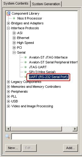
首先,我们要在NIOS II 软核中构建RS232模块。打开Quartus软件,双击进入SOPC BUILDER,然后点击下图所示红圈处,
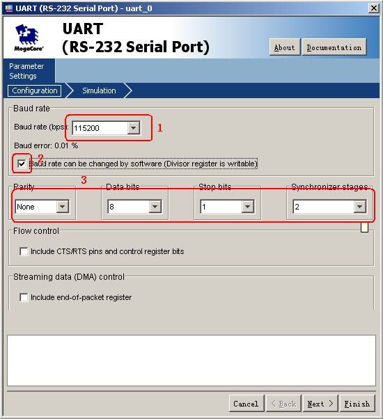
点击后,如下图所示,红圈1处为波特率,我们设置为115200;红圈2处是是否允许通过软件改变波特率,我们选中,便是允许,这样我们就可以通过软件来随时更改波特率,如果软件不设置,默认值就是上面设置的115200;红框3中是设置一些与串口有关的参数,校验方式,数据位,停止位,后面那个基本不用,大家根据实际情况来修改。设置好以后,点击Next,Finish,完成构建。
构建好以后,将其更名为RS232,然后进行自动分配地址,自动分配中断号。一切就绪,点击General,进行编译。
编译好以后,退出,进入Quartus界面,给其分配引脚,如下图所示
然后运行TCL脚本,编译,等待……
编译好以后,大家可以选择自己的方式将程序下载到FPGA中,AS或JTAG都可以。
软件开发
打开NIOS II 9.0 IDE后,按快捷键Ctrl+b编译程序,等待编译……
编译好以后,我们再来看system.h文件。可以看到rs232部分的代码了,如下表所示,红圈处就是我们要用到的部分,大家已经熟悉了,一个是基地址,一个是中断号
/*

* RS232 configuration

*

*/

#define RS232_NAME "/dev/RS232"

#define RS232_TYPE "altera_avalon_uart"

#define RS232_BASE 0x00201000

#define RS232_SPAN 32

#define RS232_IRQ 2

#define RS232_BAUD 115200

#define RS232_DATA_BITS 8

#define RS232_FIXED_BAUD 0

#define RS232_PARITY 'N'

#define RS232_STOP_BITS 1

#define RS232_SYNC_REG_DEPTH 2

#define RS232_USE_CTS_RTS 0

#define RS232_USE_EOP_REGISTER 0

#define RS232_SIM_TRUE_BAUD 0

#define RS232_SIM_CHAR_STREAM ""

#define RS232_FREQ 100000000

#define ALT_MODULE_CLASS_RS232 altera_avalon_uart
下面,我们开始编写软件程序,首先是修改sopc.h。如下表格所示
typedef struct
{
    //接收寄存器
    union{
        struct{
            volatile unsigned long int RECEIVE_DATA         :8;
            volatile unsigned long int NC                   :24;
        }BITS;
        volatile unsigned long int WORD;
    }RXDATA;
    //发送寄存器
    union{
        struct{
            volatile unsigned long int TRANSMIT_DATA        :8;
            volatile unsigned long int NC                   :24;
        }BITS;
        volatile unsigned long int WORD;
    }TXDATA;
    //状态寄存器
    union{
        struct{
            volatile unsigned long int PE                   :1;
            volatile unsigned long int FE                   :1;
            volatile unsigned long int BRK                  :1;
            volatile unsigned long int ROE                  :1;
            volatile unsigned long int TOE                  :1;
            volatile unsigned long int TMT                  :1;
            volatile unsigned long int TRDY                 :1;
            volatile unsigned long int RRDY                 :1;
            volatile unsigned long int E                    :1;
            volatile unsigned long int NC                   :1;
            volatile unsigned long int DCTS                 :1;
            volatile unsigned long int CTS                  :1;
            volatile unsigned long int EOP                  :1;
            volatile unsigned long int NC1                  :19;
        } BITS;
        volatile unsigned long int WORD;
    }STATUS;
    //控制寄存器
    union{
        struct{
            volatile unsigned long int IPE                  :1;
            volatile unsigned long int IFE                  :1;
            volatile unsigned long int IBRK                 :1;
            volatile unsigned long int IROE                 :1;
            volatile unsigned long int ITOE                 :1;
            volatile unsigned long int ITMT                 :1;
            volatile unsigned long int ITRDY                :1;
            volatile unsigned long int IRRDY                :1;
            volatile unsigned long int IE                   :1;
            volatile unsigned long int TRBK                 :1;
            volatile unsigned long int IDCTS                :1;
            volatile unsigned long int RTS                  :1;
            volatile unsigned long int IEOP                 :1;
            volatile unsigned long int NC                   :19;
        }BITS;
        volatile unsigned long int WORD;
    }CONTROL;
    //波特率分频器
    union{
        struct{
            volatile unsigned long int BAUD_RATE_DIVISOR    :16;
            volatile unsigned long int NC                   :16;
        }BITS;
        volatile unsigned  int WORD;
    }DIVISOR;

}UART_STR;
这个结构体中包括5个共用体,这5个共用体对应RS232的5个寄存器,我们来看看这5个寄存器,下图所示,这个图来自《n2cpu_Embedded Peripherals.pdf》的第6-11页
这个图中的(1)有一个说明,就是说第7,8位根据设置的数据位有所改变,我们设置数据位8位,所以7,8位与前6为性质相同。
与之前讲的PIO的结构体类似,这个结构体的内容是按上图的寄存器顺序来定义的,(因为endofpacket没用到,所以在结构中没有定义)这样在操作过程中就可以实现相应的偏移量(offset)。
在这个结构体中,我们嵌套了5个共有体,在共用体中,我们又使用了结构体和位域。头一次看的一定很头晕。其实,我们这样做的目的就是想对寄存器的每一位进行单独的控制,同时也可以实现这个寄存器的整体控制。具体应用,我们在下面的程序中会应用到。
有了上面来的结构体以后,我们需要定义一个宏,跟PIO的类似。
#define _UART


#ifdef _UART

#define UART ((UART_STR *) RS232_BASE)

#endif
不用解释了吧,在PIO部分已经解释过了,应该没什么问题了吧。
接下来,我们要在inc下建立uart.h文件,如下图所示
建好以后,对uart.h进行编写,如下表所示
/*

* =================================================================

* Filename: uart.h

* Description: The head of uart device driver

* Version:

* Created:

* Revision: none

* Compiler: Nios II IDE

*

* Author: AVIC

* Company: 金沙滩工作室

* ================================================================

*/

#ifndef UART_H_

#define UART_H_

#include "../inc/sopc.h"

#define BUFFER_SIZE 200

/*----------------------------------------------------------------

* Define

*---------------------------------------------------------------*/

typedef struct{

unsigned char mode_flag; //xmodem 1;uart 0;

unsigned int receive_flag;

unsigned int receive_count;

unsigned char receive_buffer[BUFFER_SIZE];

int (* send_byte)(unsigned char data);

void (* send_string)(unsigned int len, unsigned char *str);

int (* init)(void);

unsigned int (* baudrate)(unsigned int baudrate);

}UART_T;

extern UART_T uart;

#endif /*UART_H_*/
在上面的代码中,结构体UART_T很重要,它是模拟面向对象的一种编程思想,也是我之前说的一种很重要的编程方式。我们将与UART有关系的所有函数、变量都打包在一起,对其他函数来说,它们只能看到uart这个结构体,而里面的单独部分都是不可见的。希望大家可以好好体会其中的思想,对大家的编程一定会有很大的好处。
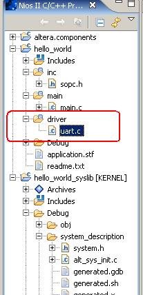
下面,我们要开始写RS232的驱动了,首先我们要在driver下面建立一个.c文件,命名为uart.c,如下图所示
建好以后,我们来编写uart.c文件,如下表所示
/*
 * =================================================================
*       Filename:  uart.c
 *
 *    Description:  RS232 device driver
 *
 *        Version:
 *        Created:
 *       Revision:  none
 *       Compiler:  Nios II IDE
 *
 *         Author:  AVIC
 *        Company:  金沙滩工作室
 * ===============================================================
 */

/*--------------------------------------------------------------
 *  Include
 *-------------------------------------------------------------*/
#include "sys/alt_irq.h"
#include "../inc/sopc.h"
#include <stdlib.h>
#include <stdio.h>
#include "../inc/uart.h"

/*--------------------------------------------------------------
 *  Function Prototype
*--------------------------------------------------------------*/
static int uart_send_byte(unsigned char data);
static void uart_send_string(unsigned int len, unsigned char *str);
static int uart_init(void);
static void uart_ISR(void);
static int set_baudrate(unsigned int baudrate);

//初始化uart结构体,大家注意结构体的初始化方式
UART_T uart={
    .mode_flag=0,
    .receive_flag=0,
    .receive_count=0,
    .send_byte=uart_send_byte,
    .send_string=uart_send_string,
    .init=uart_init,
    .baudrate=set_baudrate
};

/*
 * ===  FUNCTION  ==================================================
 *         Name:  uart_send_byte
 *  Description:  发送一个字节数据
 * ================================================================
 */
static int uart_send_byte(unsigned char data)
{
    //将接收到的数据放到接收数据寄存器内,等待状态寄存器trdy置1,当trdy置1,说明接收完毕
    UART->TXDATA.BITS.TRANSMIT_DATA = data;
    while(!UART->STATUS.BITS.TRDY);

    return 0;
}
/*
 * ===  FUNCTION  =================================================
 *         Name:  uart_send_string
 *  Description:  发送字符串数据
 * ===============================================================
 */
static void uart_send_string(unsigned int len, unsigned char *str)
{
    while(len--)
    {
        uart_send_byte(*str++);
    }
}
/*
 * ===  FUNCTION  =================================================================
 *         Name:  uart_init
 *  Description:  初始化程序
 * ==============================================================
 */
static int uart_init(void)
{
     //设置波特率为115200
    set_baudrate(115200);

     // 对控制寄存器的irrdy进行置1,表示当接收准备好后,中断使能
     UART->CONTROL.BITS.IRRDY=1;

    //清楚状态寄存器,这就是处理整个寄存器的方式,大家要注意
     UART->STATUS.WORD=0;

    //注册uart中断,ISR为uart_ISR
    alt_irq_register(RS232_IRQ, NULL, uart_ISR);

    return 0;
}

/*
 * ===  FUNCTION  ================================================
 *         Name:  uart_ISR
 *  Description:  串口中断
 * ==============================================================
 */
static void uart_ISR(void)
{
    //等待状态寄存器的接收数据状态位rrdy,当rrdy位为1时,说明新接收的值传输到了接收数据寄存器
    while(!(UART->STATUS.BITS.RRDY));

    //reveive_buffer为我们通过栈的方式在内存中开设的内存块,将接受数据寄存器中的数据到这个内存块中
    uart.receive_buffer[uart.receive_count++] = UART->RXDATA.BITS.RECEIVE_DATA;

    //当接收数据的最后一位为\n(回车符)时,进入if语句,也就是说,\n作为了结束标志符,每次发送数据后,要加一个回车符作为结束符
    if(uart.receive_buffer[uart.receive_count-1]=='\n'){
         uart.receive_buffer[uart.receive_count]='\0';
         uart_send_string(uart.receive_count,uart.receive_buffer);
         uart.receive_count=0;
         uart.receive_flag=1;
    }
}
/*
 * ===  FUNCTION  ===============================================
 *         Name:  set_baudrate
 *  Description:  设置波特率
 * ==============================================================
 */
static int set_baudrate(unsigned int baudrate)
{
    //设置波特率有一个公式的,波特率=时钟频率/(divisor+1),转换以后就是下面了。
    UART->DIVISOR.WORD=(unsigned int)(ALT_CPU_FREQ/baudrate+0.5);

    return 0;
}
编写好上面的函数以后,我们要修改main.c,如下表所示
#include "../inc/sopc.h"
#include "system.h"
#include "sys/alt_irq.h"
#include <unistd.h>
#include <stdio.h>
#include "../inc/uart.h"

int main()
{
    unsigned char buffer[50]="Hello FPGA!\n";

    //初始化串口,注意它的使用方法
    uart.init();

    //循环发送字符串
    while(1){
        uart.send_string(sizeof(buffer),buffer);
        usleep(500000);
    }

    return 0;
}
今天就讲到这,上面的讲解方式不知道大家觉得是否合适,如果有什么问题,请给我留言。
posted on 2010-03-31 19:02 FPGA黑金开发板 阅读(5124) 评论(14) 编辑 收藏 举报


