raspberrypi 与 arduino 使用 nRF24L01+ 通信 -- raspberry pi为发送端
nRF24L01+ 通过gpio与树梅派链接,按着网上能找到的所有方法基本上都不顺利,从Python方案到c方案都不行,尝试了很长时间,终于成功,基本上,每个人都会碰到各种各样的问题。
arduino 接收端代码:http://www.cnblogs.com/hangxin1940/archive/2013/05/01/3048315.html
修改系统配置
$ sudo nano /etc/modprobe.d/raspi-blacklist.conf
都注释掉,修改为:
# blacklist spi and i2c by default (many users don't need them)

#blacklist spi-bcm2708
#blacklist i2c-bcm2708
修改加载模块
$ sudo nano /etc/modules
改为:
snd-bcm2835
i2c-dev
spidev
主要是增加 spidev
重启之后,/dev/中会多出两个设备 spidev0.0 与 spidev0.1, 没有出现的话请google排错。
下载源码
https://github.com/gnulnulf/RF24
打包下载到树梅派
编译rf24库
解压下载好的源码,进入目录RF24-master/librf24-rpi/librf24
编译
$ make
如果出现缺少某些编译工具的提示,google搜搜然后apt安装就是了 安装
$ sudo make install
编译源码
$ make
安装
$ sudo make install
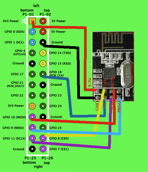
连接 nRF24L01+ 模块

rf24        rasp
3.3v        3.3v (不能使用5v)
GND         GND
CE          GPIO 18 (右排往下第六个)
CSN         GPIO 8 (右排往下倒数第二个)
SCK         GPIO 11 (左排往下倒数第二个)
MOSI        GPIO 10 (左排往下倒数第四个)
MISO        GPIO 9  (左排往下倒数第三个)
编写发送端程序
源码中已经有丰富的示例程序,我们只需要改改源码就可以跑通
进入librf24-rpi/librf24/examples
更改 pingtest.cpp 代码为:
/**
* Example RF Radio Ping Pair
*
* This is an example of how to use the RF24 class. Write this sketch to two different nodes,
* connect the role_pin to ground on one. The ping node sends the current time to the pong node,
* which responds by sending the value back. The ping node can then see how long the whole cycle
* took.
*/
#include <cstdlib>
#include <iostream>
#include "../RF24.h"
/*
连接方法
rf24 rasp
3.3v 3.3v (不能使用5v)
GND GND
CE GPIO 18 (右排往下第六个)
CSN GPIO 8 (右排往下倒数第二个)
SCK GPIO 11 (左排往下倒数第二个)
MOSI GPIO 10 (左排往下倒数第四个)
MISO GPIO 9 (左排往下倒数第三个)
*/
//
// 硬件配置
// spi设备、CSN速率、CSN引脚 GPIO 8
RF24 radio("/dev/spidev0.0",8000000 , 8);
// 设置数据通道地址
const uint64_t pipes[2] = { 0xF0F0F0F0E1LL, 0xF0F0F0F0D2LL };
// 配置rf24
void setup(void) {
printf("\n\rRF24/examples/pingpair/\n\r");
printf("ROLE: Ping out\n\r");
radio.begin();
// 开启动态有效信息长度
radio.enableDynamicPayloads();
// 设置重传次数以及每次重传的延迟
//radio.setRetries(15,15);
// 设置传输速率
radio.setDataRate(RF24_1MBPS);
// 设置功放级别,有四种级别:
// RF24_PA_MIN=-18dBm
// RF24_PA_LOW=-12dBm
// RF24_PA_MED=-6dBM
// RF24_PA_HIGH=0dBm
radio.setPALevel(RF24_PA_HIGH);
// 设置信道(0-127)
radio.setChannel(110);
// 设置crc校验长度
// 两种 8位RF24_CRC_8 和 16位RF24_CRC_16
radio.setCRCLength(RF24_CRC_16);
radio.openWritingPipe(pipes[0]);
radio.openReadingPipe(1,pipes[1]);
//
// 开始监听
//
radio.startListening();
// 打印配置信息
radio.printDetails();
}
void loop(void) {
// 首先停止监听
radio.stopListening();
// 获取时间,并发送时间
unsigned long time = __millis();
printf("Now sending %lu...",time);
// 是否发送成功
bool ok = radio.write( &time, sizeof(unsigned long) );
if (ok)
printf("ok...");
else
printf("failed.\n\r");
// 继续监听
radio.startListening();
// 等待对方返回数据,超时时间 250ms
unsigned long started_waiting_at = __millis();
bool timeout = false;
while ( !radio.available() && !timeout ) {
//稍微延迟一下,等待radio.available()检测有效数据
__msleep(5);
if (__millis() - started_waiting_at > 200 )
timeout = true;
}
// 是否超时
if ( timeout ) {
printf("Failed, response timed out.\n\r");
} else {
// 读取返回信息,并打印出来
unsigned long got_time;
radio.read( &got_time, sizeof(unsigned long) );
printf("Got response %lu, round-trip delay: %lu\n\r",got_time,__millis()-got_time);
}
//延迟一会儿
sleep(1);
}
int main(int argc, char** argv) {
setup();
while(1)
loop();
return 0;
}
然后编译:
$ make
之后,这几个示例都会编译出来。运行pingtest程序
$ sudo ./pingtest
rasp的输出:
RF24/examples/pingpair/
ROLE: Ping out
SPI device   = /dev/spidev0.0
SPI speed    = 8000000
CE GPIO  = 8
STATUS       = 0x0e RX_DR=0 TX_DS=0 MAX_RT=0 RX_P_NO=7 TX_FULL=0
RX_ADDR_P0-1     = 0xf0f0f0f0e1 0xf0f0f0f0d2
RX_ADDR_P2-5     = 0xe2 0xe3 0xf1 0xf2
TX_ADDR      = 0xf0f0f0f0e1
RX_PW_P0-6   = 0x20 0x20 0x20 0x20 0x20 0x20
EN_AA        = 0x3f
EN_RXADDR    = 0x3e
RF_CH        = 0x6e
RF_SETUP     = 0x04
CONFIG       = 0x0f
DYNPD/FEATURE    = 0x3f 0x04
Data Rate    = 1MBPS
Model        = nRF24L01+
CRC Length   = 16 bits
PA Power     = PA_HIGH
Now sending 1607486530...failed.
Got response 1607486430, round-trip delay: 156
Now sending 1607487589...failed.
Got response 1607487489, round-trip delay: 158
Now sending 1607488650...failed.
ps: 本人用arduino uno充当接收端时,发送端总是提示发送失败failed,但是,双方通信是没问题的。换成了lilypad就没有这个情况。
上面的是配置信息,如果大部分数据都是ffffff,那么硬件没有配置成功,这样很麻烦,只能求助与google了。
下面的 sending那些东西,是发送给arduino,以及arduino返回的数,arduino会给每个数减去100,并返回。
arduino的输出:
RF24/examples/pingpair/
ROLE: Pong back
STATUS       = 0x0e RX_DR=0 TX_DS=0 MAX_RT=0 RX_P_NO=7 TX_FULL=0
RX_ADDR_P0-1    = 0xf0f0f0f0d2 0xf0f0f0f0e1
RX_ADDR_P2-5    = 0xc3 0xc4 0xc5 0xc6
TX_ADDR      = 0xf0f0f0f0d2
RX_PW_P0-6      = 0x20 0x20 0x00 0x00 0x00 0x00
EN_AA        = 0x3f
EN_RXADDR       = 0x03
RF_CH        = 0x6e
RF_SETUP        = 0x05
CONFIG       = 0x0f
DYNPD/FEATURE   = 0x3f 0x04
Data Rate    = 1MBPS
Model        = nRF24L01+
CRC Length   = 16 bits
PA Power     = LA_MED
Got payload 1607938782...Sent response.
Got payload 1607939839...Sent response.
Got payload 1607940898...Sent response.
补充
http://wenku.baidu.com/view/6c779635eefdc8d376ee3256.html nRF24L01中文手册
http://maniacbug.github.io/RF24/classRF24.html RF24的api手册,适用于rasp和arduino
其他 rf24与rasp和arduino相关的资源:
http://www.raspberrypi.org/phpBB3/viewtopic.php?t=17061 官方讨论
https://github.com/maniacbug/RF24 rf24库
https://github.com/gnulnulf/RF24 包含rasp的rf24库
https://bitbucket.org/Amanoo/rf24rp/wiki/Home BeagleBone的rf24库移植的rasp库
http://www.e-risingstar.com/wordpress/?p=543 另一个rasp与arduino的互通指南,基于上面那个BeagleBone移植过来的库
https://plus.google.com/100198871098258549028/posts/Hn1JpyUWKKo rasp的python rasp库
http://arduino-info.wikispaces.com/Nrf24L01-2.4GHz-HowTo arduino的rf24指南
http://maniacbug.wordpress.com/2011/11/02/getting-started-rf24/ 另一个arduino的rf24指南


【推荐】编程新体验,更懂你的AI,立即体验豆包MarsCode编程助手
【推荐】凌霞软件回馈社区,博客园 & 1Panel & Halo 联合会员上线
【推荐】抖音旗下AI助手豆包,你的智能百科全书,全免费不限次数
【推荐】博客园社区专享云产品让利特惠,阿里云新客6.5折上折
【推荐】轻量又高性能的 SSH 工具 IShell:AI 加持,快人一步