WPF 3D基础(1)
2010-12-23 13:34 Clingingboy 阅读(11777) 评论(2) 收藏 举报
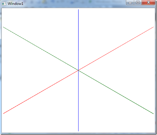
构建3D坐标系
使用3D Tools构建3D坐标系
            <Viewport3D>
                <Viewport3D.Camera>
                    <PerspectiveCamera Position="-2,2,2" LookDirection="2,-2,-2" UpDirection="0,1,0"/>
                </Viewport3D.Camera>
                <!--x-->
                <tools:ScreenSpaceLines3D Points="-10,0,0 10,0,0" Thickness="1" Color="Red"></tools:ScreenSpaceLines3D>
                <!--y-->
                <tools:ScreenSpaceLines3D Points="0,-10,0 0,10,0" Thickness="1" Color="Blue"></tools:ScreenSpaceLines3D>
                <!--z-->
                <tools:ScreenSpaceLines3D Points="0,0,-10 0,0,10" Thickness="1" Color="Green"></tools:ScreenSpaceLines3D>
            </Viewport3D>
使用MeshGeometry3D建立三角形
                <ModelVisual3D>
                    <ModelVisual3D.Content>
                        <GeometryModel3D>
                            <GeometryModel3D.Geometry>
                                <MeshGeometry3D Positions="1,0,0 0,-1,0 0,0,1"/>
                            </GeometryModel3D.Geometry>
                            <GeometryModel3D.Material>
                                <DiffuseMaterial Brush="Yellow" />
                            </GeometryModel3D.Material>
                        </GeometryModel3D>
                    </ModelVisual3D.Content>
                </ModelVisual3D>
这里介绍MeshGeometry的属性
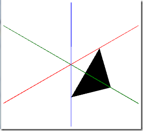
Positions表示三维坐标系顶点坐标,以空格为间隔.那么这三个坐标则为
- 1,0,0(红线右正)
- 0,-1,0(蓝线上正)
- 0,0,1(绿线右正)
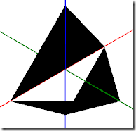
效果如下
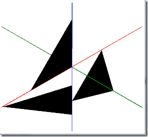
画多个三角形
坐标点必须是3的倍数,如下
                                <MeshGeometry3D Positions="
                                                1,0,0 0,-1,0 0,0,1
                                                -1,0,0 0,0,0 0,1,0
                                                -1.5,0,0 0,-1.5,0 0,-0.5,0"/>
坐标索引(TriangleIndices)
默认情况下画三角形,以第0个坐标点为索引值.
TriangleIndices可以让我们改变画三角形坐标点的索引值,比如4个坐标点,本来是0,1,2,第4个坐标点将无效,这里可以将坐标点看做储备坐标,用每3个坐标点拼凑三角形
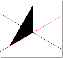
如画出上面3个三角形的其中一个,那么索引就是3,4,5(从0开始)
                                <MeshGeometry3D Positions="
                                                1,0,0 0,-1,0 0,0,1
                                                -1,0,0 0,0,0 0,1,0
                                                -1.5,0,0 0,-1.5,0 0,-0.5,0"
                                                TriangleIndices="3,4,5"/>
再如下例子,利用坐标索引构建不同形状的三角形
                                <MeshGeometry3D Positions="
                                                1,0,0 0,-1,0 0,0,1
                                                -1,0,0 0,0,0 0,1,0
                                                -1.5,0,0 0,-1.5,0 0,-0.5,0"
                                                TriangleIndices="3,1,2,0,1,2,3,0,5"/>
利用多个三角形构建多边形
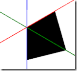
2个三角形就可以构成一个4边形,同理也可以构建多边形
                                <MeshGeometry3D Positions="
                                                1,0,0 0,-1,0 0,0,1
                                                1,0,0 0,0,0 0,-1,0
                                                "/>
效果图
两个面的平面(BackMaterial)
如一张纸有两个面
                        <GeometryModel3D>
                            <GeometryModel3D.Geometry>
                                <MeshGeometry3D Positions="
                                                -0.5,0.5,-0.5
                                                -0.5,-0.5,-0.5
                                                -0.5,-0.5,0.5
                                                -0.5,-0.5,0.5
                                                -0.5,0.5,0.5
                                                -0.5,0.5,-0.5
                                                "/>
                            </GeometryModel3D.Geometry>
                            <GeometryModel3D.Material>
                                <DiffuseMaterial>
                                    <DiffuseMaterial.Brush>
                                        <SolidColorBrush Color="Red" Opacity="1"/>
                                    </DiffuseMaterial.Brush>
                                </DiffuseMaterial>
                            </GeometryModel3D.Material>
                            <GeometryModel3D.BackMaterial>
                                <DiffuseMaterial>
                                    <DiffuseMaterial.Brush>
                                        <SolidColorBrush Color="Blue" Opacity="1"/>
                                    </DiffuseMaterial.Brush>
                                </DiffuseMaterial>
                            </GeometryModel3D.BackMaterial>
                        </GeometryModel3D>
用旋转测试就能看出其效果
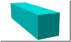
透视立方体
如果一个立方体的正面和背面的颜色不同,我们无法肉眼看到背面,如下图
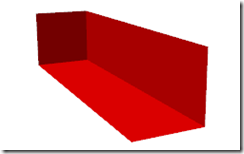
如果默认不设置Material属性的话,则会显示背面的颜色
                        <!--<GeometryModel3D.Material>
                            <DiffuseMaterial Brush="Cyan" />
                        </GeometryModel3D.Material>-->

                        <GeometryModel3D.BackMaterial>
                            <DiffuseMaterial Brush="Red" />
                        </GeometryModel3D.BackMaterial>




 浙公网安备 33010602011771号